- Print
- DarkLight
- PDF
The KeyLight tool chapter introduces the various KeyLight tools which are described in more detail in the following chapters, excluding the Network follower  , Work program (and Work program type)
  , Exchange area
  and KeyLight Annotations
 tools, which are explained in the end of this chapter.

The street light network includes point and line tools and tools for network maintenance and other purposes.
The forms for managing point objects are:
Telecom premises
Splice
Manhole
Other objects 
Pole
Streetlight 
The forms for managing line objects are:
Cable button
Conduit button
Information related to the maintenance of network objects is processed using these forms:
Premises inspection
Pole inspection
Cable inspection
The other tools listed in this chapter are:
Network follower 
Work program (and Work program type) 
Exchange area 
KeyLight Annotations
The functions and information content on the forms are the same, meaning that objects are handled in the same way, but the object form is different for each object. Depending on your user privileges, you can, for example, search for objects based on search criteria, modify their location and property values, and locate them on the map. The button functions related to forms used for managing objects are introduced in the chapter Buttons on object forms. Some object forms include buttons that have functions not available on other forms. These functions are introduced in this chapter after providing instructions applicable to all forms.
Property attributes
The object you are managing determines the form that will open. Regardless of the applicable type and object form, objects have similar property attributes. Such information is related to the object owner, its properties, location, area, and plan.
If you want to create a new point object (premises, manhole, splice, pole) or conduit, the required information include Type and Usage state. For cables, the mandatory elements are Type, Installation type, and Usage state. Required data fields are indicated in yellow on the forms. Certain information elements are updated automatically when a new object is created. For example, when you create a new cable, it gets a Length and Database ID.
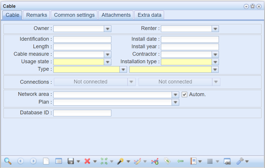
After entering the mandatory data, click Create  to create the object on the map. When the object was created successfully, the following text is displayed at the bottom of the form: Saved successfully. You can then update other property values for the object and save them in the system by clicking Save form
  .
.
The property values that can be specified vary depending on the object. For example, for a pole, you can enter information on its material, warranty period, and connection enclosures. For all objects, you can specify the owner, renter, and installation year. In addition, you can freely include text on the Comments tab.
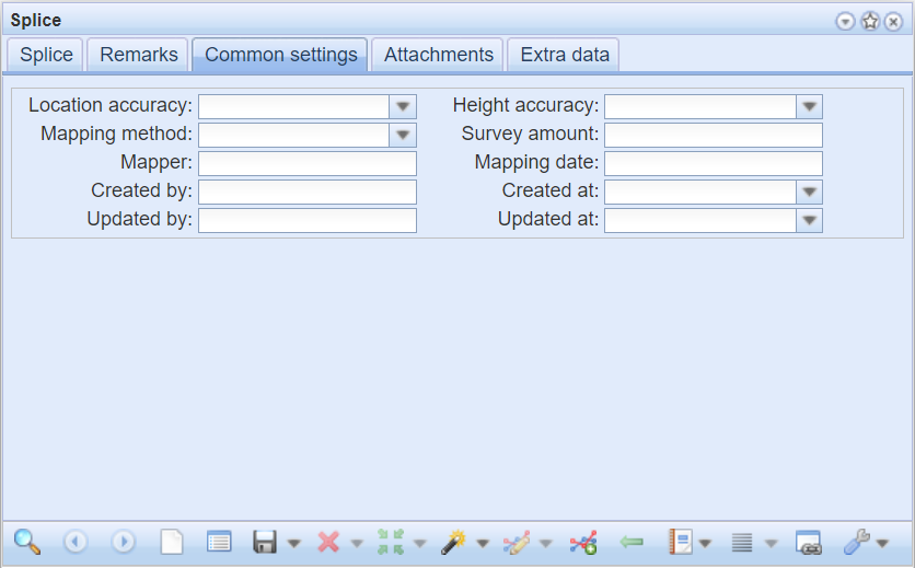
The Common tab has the same data content for all objects. On this tab, you can enter information on mapping and its accuracy, in addition to which the tab includes information about the creator and updater of the object and the creation and update dates. This information is automatically saved in the system, and it cannot be edited.
Network follower
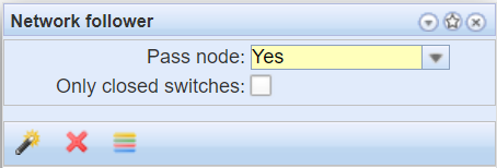
The Network follower  tool can be used to follow the desired part of the network on the map. On the form, specify the direction of following and whether the network will be followed across nodes or not. In addition, you can specify whether network following occurs over connected cables only by checking the Only closed switches checkbox. Network following requires cables and nodes to be connected to each other in the database.
Start network following with either a cable or a node. The network object from which following will be started is selected with the Select the target  function. Select the cable or node you want by specifying an area on the map with the left mouse button. A list of the found objects will be displayed.
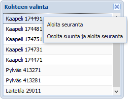
To start following, place the mouser cursor on the selected object, click the right mouse button, and select Start the network follower. The network will then be followed in both directions. When you select a cable, you can indicate a direction on the map in which direction the network is followed. To do this, click Point the direction and start the operation. The followed network will be highlighted on the map. To stop following, click Clear map layer  or close the Network follower form.
When you select Premises as the starting point for network following, the function highlights all outputs of the premises in the map window. Network follower works the same way for premises as the Highlight premises’ outputs  function on the Premises form (see Premises for more information).
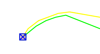
To get a list of network follower objects, click the Show in groupdisplay  button. Group display and its features are discussed in more detail in the chapter Group display.
Work programs
Work program information is processed and network objects are added to the program with the Work program  form available under KeyLight
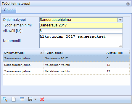
  Tools. The work program form is divided into three parts. The top section of the form includes general information on the work program: The Program type, e.g. maintenance/repair/renovation/group replacement program, and a more detailed description of the work program. This data is maintained on a separate Work program types
  form, on which admin users can add new work program types and work programs to the system. Adding new work program types
  is described in the chapter Adding work program types.
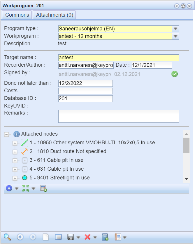
Maintenance programs include, for example, recurring maintenance work. Repair programs refer to network objects awaiting repair but not requiring immediate action. Renovation programs include objects awaiting renovation: Renovation programs can be created for future use, to which objects to be renovated can be added. Group replacement programs for lamps are created for annual group replacements, and the light points to be replaced at any time are added to them.
In addition to the information in the work program, you need to enter the information about the work program object on the form and add the network objects that belong to the objects. The object of the work program refers to a job done in one go. For example, a renovation program for a given year consists of several different renovation objects.
The network objects that are part of the work program are listed in the Attached nodes  list at the bottom of the form. The objects are shown as a list, and additional details on a row is available via the
  button. If there are multiple objects, you can scroll through them with the scroll bar.
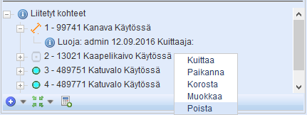
The object’s sequence number, ID, type, and usage state are displayed. Click the  button in front of the object to get information about the creator of the object, the date of association, and the party acknowledging it. Use the selection list accessible with the right mouse button to locate, highlight, acknowledge, modify, or delete an object. Click Locate to center the map on the object in question. If you have highlighted all the associated ducts and nodes on the map, you can click Highlight to highlight an individual object so that you can distinguish it from the others.
Use the Signed by button to mark a work program as completed. Once a work program has been signed, the name of the party acknowledging the object and the date of signing will appear in the Signed by
 section on the form. This will also increase the date in the To do before field by the number of days in the work program’s interval, counted from the date of acknowledgement.

Adding objects to work programs
There are three ways to add objects to a work program:
On the Work program form, click the Attach an element button and select the object on the map. If the specified area contains more than one option, choose the desired object in the Object selection window.
or
By retrieving the desired objects to the object form and clicking the Take to Work program button on the form, all objects retrieved to the object form are transferred to the work program.
or
Add an object with the actions in the Attach an element drop-down menu’s list.
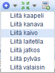
- Open the desired object form via the list and use its search features to retrieve the objects to be added to the work program.
Adding several objects to a work program:
For example, when you want to add all streetlight poles of a specific area to a work program.
- Click the Attach an element
 drop-down menu (Add pole) to open the Pole form.
 - Retrieve all poles of the area to the form, for example, with the Free area function in the Pick from map
 drop-down menu. The search functions of the forms are described in chapters Retrieving information to a form and Picking objects from the map.
 - Move the objects retrieved to the form to the Work program form using the Export to work program
 button on the Pole form.

Adding a work program type
Work programs can be added in the system using the Work program type form. Select a program type for the work program and enter the Work program’s name, Time period (months) and any free-form comments. When you click the Save button, the work program types created are listed at the bottom of the form. Select a row to edit its program type information or delete  the work program type from the system.
Exchange area
You can add and edit exchange areas with the Exchange area form. In the KeyLight tools, click Exchange area
  to open a window for managing exchange areas.
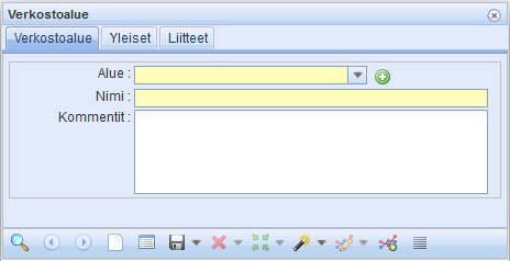
To create a new exchange area, take the following steps:
- Select the area in the drop-down menu. If you cannot find the area in the menu, click Add new area
 to create a new area. On the form that is displayed, enter the name of the new exchange area and click Add. After this, the network area that was created will be selected on the form.
 - Enter a name and optional comments for the network area.
- Click the Save
 or Create New
  button to create an exchange area on the map. If you try to create a new exchange area with a name that already exists, the program notices this and retrieves it to the previous form without creating a copy with the same name.

The exchange area/area is added using the Exchange area drop-down menu on the object form.

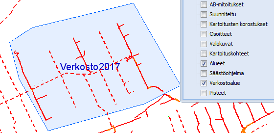
Use the Layers – Layers selection tool to show the areas on the map. Zoom in on the map to see the names of the areas.
Annotations
The KeyLight environment allows you to add Annotations  to the map view. You can add an annotation to objects placed on the map, such as cables, nodes, conduits, and light points. Annotations
  can be found in the Network tools
  drop-down menu.

The creation of annotations is illustrated below using a few examples.
Cable annotation
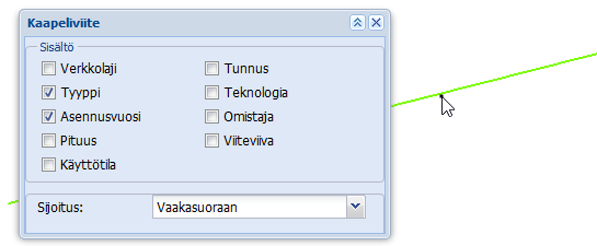
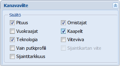
In KeyLight annotations, click the Cable annotation  button. This will display the Cable annotation form, where you can change the information content of the annotation its presentation on the map. To add an annotation to the map, first select a cable on the map for which you want to create an annotation and point at the location in which you want to place the annotation.
You can change the information content of the annotation on the Cable annotation form by checking or unchecking the desired checkboxes. The settings, i.e., the checkbox states, are stored in the browser’s memory as cookies.
If more than one object is located at the point of left clicking, the Object selection window will appear. Left-click the item on the list to highlight it on the map. Right-click the object and then click Annotate and indicate the location for the annotation. You can also select an object in the Object selection window by double-clicking its row, and then place the annotation at the desired location.
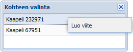
Annotate node
Node annotations allow you to create annotations for point objects, such as splices and poles. In the Annotate node window that opens, select the content of the annotation and place it on the map.
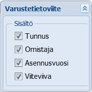
Conduit annotations
Conduit annotations allow you to create annotations for conduits. In the Conduit annotation window that opens, select the content of the annotation and place it on the map. For more information, see Cable annotation.
Annotate leavenumber
In KeyLight annotations, click Annotate leavenumber  and click the desired cable. Specify a location for the annotation on the map.
Streetlight and lamp power
Printing the power (W) of a streetlight or lamp on the map can be activated via the Light point annotation drop-down menu. The power value is printed on the map if it has been saved for the lamp.

To print the power of a lamp on the map, click the pole/light point on the map.
If there are more than one streetlight on the pole, select the streetlight whose lamp power you want to print on the map in the list that opens. The selected direction of the streetlight is highlighted on the map. Select the streetlight either by double-clicking it on the selection list or by right-clicking it and then clicking Choose in the context menu. Then click the location of the annotation on the map.

Group annotations
Use the Annotate group  button to aggregate information about multiple cables and conduits in a single annotation. Select the cables and conduits for the annotation with the left mouse button by first clicking a map object at one extreme of the area and then a map object at another extreme of the map. Information about these objects and the cables and conduits that fall between them is printed in the annotation. Finally, click the place for the annotation with the left mouse button. In other words, you need three clicks to create an annotation. You can select content to print on the annotation for cables or ducts or both in the Group annotation window (type, installation year, length, ID, usage state, and technology).
In the figure below, group annotations are used to combine information on several conduits and cables into one annotation. To create an annotation, a cable was selected first (lower line), and then a conduit was selected (upper line). If there were other cables or conduits between the selected objects, information on them would also be added into the annotation.

Mass update of annotations
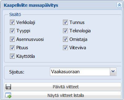
Multiple cable and conduit annotations can be updated in one go. This function is particularly useful when you change the placement scale menu or want to change the information content of annotations. Open annotation mass update via the cable or conduit annotation’s drop-down menu.
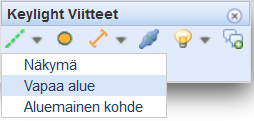
You can perform the mass update of annotations based on either 1) Map view area, 2) Free area, or 3) Existing area:
- Map view area: Annotations that are displayed in the map view are updated.
- Free area: Use the left mouse button to draw an area within which annotations are updated. Click the right mouse button to end drawing.
- Existing area: Use the left mouse button to click a point within an existing area to open the Object selection window. Double-click an area’s name on the list to select the required area. Please note that you must have Areas active in Layers in order to have the areas displayed on the map!
Select the information content you want to view on the map. After this, click Update annotations  to mass update all annotation information on the map. Alternatively, you can click
  Open annotations to list to open the Annotations form. On the Annotations form, you can select the annotations that you want to update. The Annotations form is discussed in more detail in the chapter Selecting annotations.
Edit annotation location
Use the Edit annotation location  tool to change the location of annotations.
- On the map, specify the area containing the annotations you want to move.
- Click the map to start moving the selected annotations, highlighted with the
 symbol.
 - Move annotations by dragging the red square
 on the map. The annotations will be moved relative to the location of the point.
 - Accept the new location by clicking the right mouse button. In the Confirm move window that appears, click Save. Click Cancel to cancel the move.
Deleting annotations
You can delete individual or multiple annotations from the map view or a specific area using the Delete annotation  button. In addition, you can also select the annotations you want to delete from the Annotations list.
- To delete an annotation, first click Delete annotation
 .
. - On the map, select the annotation you want to delete. If you want to delete multiple annotations, use the left mouse button to draw a rectangle on the map, within which annotations are to be deleted. The annotations that will be deleted are highlighted on the map.
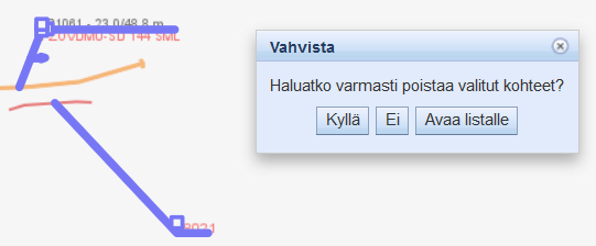
- The program will ask you to confirm the deletion of the annotation. If you want to view the annotations that are to be deleted, click Open annotations to list. On the displayed Annotations list, you can delete or update annotations as required. Additional options provided by the Annotations list are discussed in the chapter Selecting annotations.
TIP: An annotation is automatically deleted when its object is deleted.
Mass deletion of annotations
Go to the drop-down menu of Delete annotation  to activate the mass deletion of annotations.
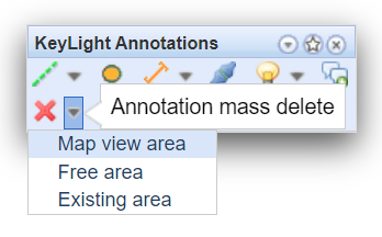
You can perform a mass deletion of annotations based on either 1) Map view area, 2) Free area, or 3) Existing area:
- Map view area: Annotations that are displayed in the map view will be deleted.
- Free area: Use the left mouse button to draw an area within which annotations are deleted. Click the right mouse button to end drawing.
- Existing area: Use the left mouse button to click a point within an existing area to open the Object selection window. Double-click an area’s name on the list to select the required area. Please note that you must have Areas active in Layers in order to have the areas displayed on the map!
The annotations that will be deleted are highlighted on the map. The program will ask you to confirm the deletion. In addition, you can open the annotations to be deleted on the list view by clicking Open annotations to list.
Selecting annotations
When performing a mass update or mass deletion, you can select the annotations you want to delete by first specifying the area within which annotations are to be deleted. After this, select the annotations that you want to update for the object set:
- When performing a mass update, click Open annotations to list.
- When performing a mass deletion, click Open to list.
Both options take you to the Annotations form. On the Annotations form, you can select the annotations that you want to update ( Update all) or delete (
 Delete all). Please note that you cannot select the Update all function when performing a mass deletion.
In the figure below, the user has clicked Open annotations to list when performing a mass update of conduits.
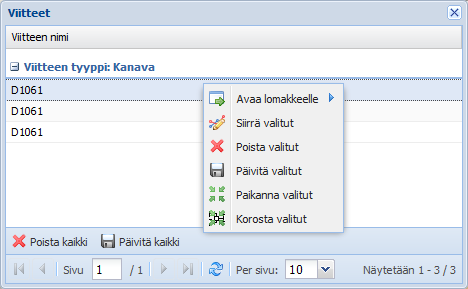
On the list of annotations, select the required rows while holding down the Control or Shift key. Click the right mouse button to access the following functions: open the selected objects on their forms and delete, update, locate, or highlight the selected objects.
Use the  Move selected function to move annotations on the map to a new location. Further information on this function is available in the chapter Edit annotation location.

 drop-down menu (Add pole) to open the Pole form.
 drop-down menu. The search functions of the forms are described in chapters
  button on the Pole form.
 to create a new area. On the form that is displayed, enter the name of the new exchange area and click Add. After this, the network area that was created will be selected on the form.
 or Create New
  button to create an exchange area on the map. If you try to create a new exchange area with a name that already exists, the program notices this and retrieves it to the previous form without creating a copy with the same name.
 symbol.
 on the map. The annotations will be moved relative to the location of the point.
 .
.