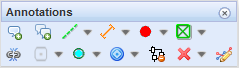
Use the tools in the Annotations toolbar to create various annotations for map objects. The form that is displayed when you click the Annotations button includes tools for deleting an annotation and for creating an annotation for a single object or multiple objects simultaneously.
Annotations are updated automatically when object data is updated. The maximum number of mass update and deletion of annotations is 100: you can delete or update a maximum of 100 annotations at a time. This setting can be changed through the admin user interface. The annotations that are updated are highlighted on the map. You can select annotations for updating on a separate annotation list, which includes information on the annotation’s type and text.
You can filter annotations so that they are displayed or hidden with the plan. If even one of the objects included in a group annotation is linked to a plan, the entire annotation will be displayed. When you select layers in the Layers tool, select Filters – Plan.
Creating an annotation
- Use the Annotate object
 tool to create an annotation for any objects that support annotations. The object’s own settings are used.
 - On the map, select the object you want to annotate. If there are multiple objects that can be selected, double-click or right-click to select the appropriate object on the list and select Annotate. Left-click to highlight the object on the map.
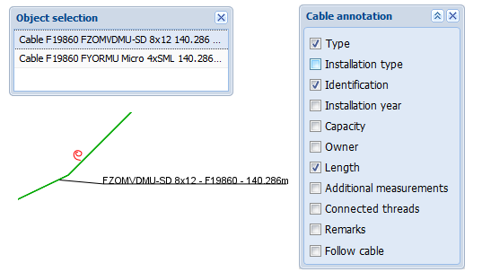
- In the dialogue box for Annotation, select the required items. Note that the available options vary depending on the selected annotation tool. Below you can see a Cable annotation as an example.
- Use the left mouse button to position the annotation on the map. During the creation and positioning of an annotation, the annotation text is displayed on the map. This makes it easier to find an appropriate location for it.
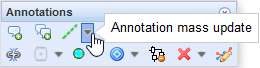
Mass update of annotations
You can perform a mass update of annotations (excluding group annotations and sheath annotations). This function is particularly useful when you change the placement scale menu or want to change the information content of annotations.
You can find the Mass update of annotations function in the drop-down menu for each annotation object (cable, conduit, splice, telecom premises, manhole, pole or point object.
You can perform the mass update of annotations based on either 1) Map view area, 2) Free area, or 3) Existing area:
- Map view area: Annotations that are displayed in the map view are updated.
- Free area: Use the left mouse button to draw an area within which annotations are updated. Click the right mouse button to end drawing.
- Existing area: Use the left mouse button to click a point within an existing area to open the Object selection window. Double-click an area’s name on the list to select the required area. Please note that you must have Areas active in Layers in order to have the areas displayed on the map!
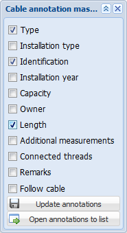
Select the information content you want to view on the map. Then, click Update annotations to mass update all annotation information on the map. Alternatively, you can click Open annotations to list
 to open the Annotationsform. On the Annotations form, you can select the annotations that you want to update. The Annotationsform is discussed in more detail in the chapter Selecting annotations.
Deleting annotations
You can delete annotations one-by-one or as a mass deletion based on the map view or a defined area. In addition, you can also select the annotations you want to delete from the Annotations list.
- To delete an annotation, first click Delete annotation
 .
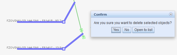
. - On the map, select the annotation you want to delete. If you want to delete multiple annotations, use the left mouse button to draw a rectangle on the map, within which annotations are to be deleted. The annotations that will be deleted are highlighted on the map.
The program will ask you to confirm the deletion of the annotation. If you want to view the annotations that are to be deleted, click Open annotations to list. On the displayed Annotations list, you can delete or update annotations as required. Additional options provided by the Annotations list are discussed in the chapter Selecting annotations.
TIP: An annotation is automatically deleted when its object is deleted. A group annotation is deleted when all the related objects have been deleted.
Mass deletion of annotations
Go to the drop-down menu of Delete annotation to activate the mass deletion of annotations. You can perform a mass deletion of annotations based on either 1) Map view area, 2) Free area, or 3) Existing area:
- Map view area: Annotations that are displayed in the map view will be deleted.
- Free area: Use the left mouse button to draw an area within which annotations are deleted. Click the right mouse button to end drawing.
- Existing area: Use the left mouse button to click a point within an existing area to open the Object selection window. Double-click an area’s name on the list to select the required area.Please note that you must have Areas active in Layers in order to have the areas displayed on the map
The annotations that will be deleted are highlighted on the map. The program will ask you to confirm the deletion. In addition, you can open the annotations to be deleted on the list view by clicking Open annotations to list.
Selecting annotations
When performing a mass update or mass deletion, you can select the annotations you want to delete by first defining the area within which annotations are to be deleted and then picking from this group the objects and annotations that you want to update:
- When performing a mass update, click Open annotations to list.
- When performing a mass deletion, click Open to list.
Both options take you to the Annotations form. On the Annotations form, you can select the annotations that you want to update ( Update all ) or delete ( Delete all
 ). Please note that you cannot select the Update all function when performing a mass deletion.
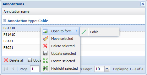
On the list of annotations, select the required rows while holding down the Control or Shift key. Click the right mouse button to access the following functions: open the selected objects on their forms and delete, update, locate, or highlight the selected objects.
Use the Move selected function to move annotations on the map to a new location. Further information on this function is available in the chapter Edit annotation location.
Edit annotation location
Use the Edit annotation location tool to change the location of annotations.
- On the map, define the area containing the annotations you want to move.
- Click the map to initiate the moving of annotations.
- Move annotations by dragging the red square
 on the map. The annotations will be moved relative to the location of the point.
 - Accept the new location by clicking the right mouse button. In the displayed window, click Save. Click Cancel to cancel the move.
Group annotations
- Annotate group
 lets you combine the information on several cables (type, length, and identifier) and conduits (conduit identifier, duct types, and conduit length) into one annotation.
 - To select the cables and conduits you want to include in an annotation, click on both sides of the required objects in order to include in the annotation the information on the cables and conduits between the points you clicked.
- Position the annotation on the map.
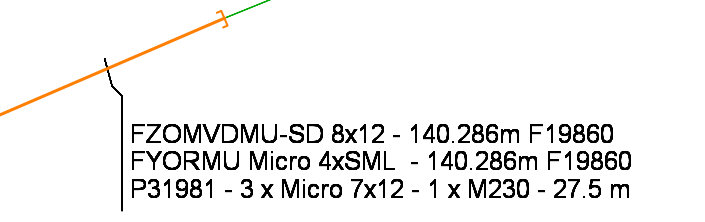
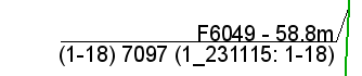
Group annotations are used to combine information on several conduits and cables into one annotation. To create an annotation, a cable was selected first (lower line), and then a conduit was selected (upper line). If there were other cables or conduits between the selected objects, information on them would also be added into the annotation.
Cable annotations
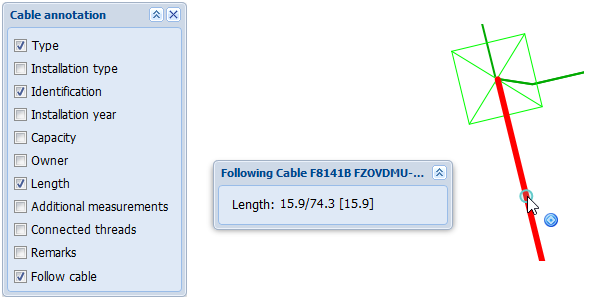
Click Cable annotation to annotate a cable. Creating an annotation is carried out mainly as described in the chapter Creating an annotation. However, note the Follow cable setting that is illustrated below. The settings available for cable annotations are illustrated.
- Type: The annotation includes the cable type
- Installation year: Cable installation year
- Installation type: The cable installation type (buried, aerial, submarine, tunnel, etc.)
- Capacity: The maximum capacity of the cable
- Owner: Owner of the cable
- Length: The length of the cable
- Additional measurement: Distance from both ends of the cable, and the cable reading at the annotated point. Takes into account the provided additional lengths (loops/coils)
- Connected threads: The logical connections of the cable
- Remarks: Comments related to the cable
- Follow cable: Select the cable that is highlighted on the map. Cable lengths are displayed in the Following Cable window. Position the cable annotation at the appropriate point on the cable route. Cable lengths are discussed in more detail in the chapter Cable length, extra length, and total length.
The Connected threads function of the cable annotation displays the connected pairs of the cable, the identifier of the telecom premises/splice, the identifier of the device and connectors.
Conduit annotations
Click Conduit annotation to annotate a conduit as described in the chapter Creating an annotation. Take into account the settings available for conduit annotations:
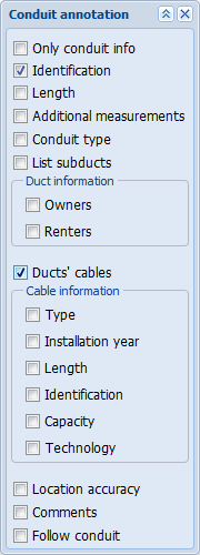
- Only conduit info: The annotation only includes the selected conduit information
- Identification: Conduit identifier
- Length: The conduit’s length
- Additional measurements: The distance from both ends of the cable and the cable reading at the annotated point. Take into account the entered additional lengths (loops/coils)
- Conduit type: The conduit’s type
- List sub-ducts: Sub-ducts in the conduit
- Duct information – Owners: Owners of the duct
- Duct information – Renters: Renters of the duct
- Cables in a duct: The annotation includes information on the cables located in the conduit’s ducts.
- Cable information – Type: Cable type
- Cable information – Installation year: The cable installation year
- Cable information – Length: Cable length
- Cable information – Identification: Cable identifier
- Cable information – Capacity: Maximum capacity of the cable
- Cable information – Technology: Cable technology
- Location accuracy: The location accuracy of the conduit
- Remarks: Comments related to the conduit
- Follow conduit: Select the conduit that is highlighted on the map. Conduit lengths are displayed in the Following Conduit window. Position the conduit annotation at the appropriate point on the conduit route. See Cable length, extra length, and total length.
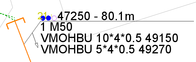
The completed conduit annotation displays the conduit profile, and an arrow points in the viewing direction of the profile.
Splice annotation
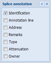
Click Splice annotation to annotate a splice. This annotation is created mainly as described in the chapter Creating an annotation. The settings available for splice annotations are as follows:
- Identification: Splice identifier
- Annotation line: Select whether an annotation line is drawn
- Address: Address of the splice
- Remarks: Comments related to the splice
- Type: Splice type
- Attenuation: Splice’s attenuation in decibels
- Owner: Owner of the splice
Telecom premises annotations
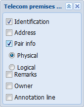
Click Telecom premises annotation to annotate telecom premises. This annotation is mostly created as described in chapter Creating an annotation. The settings available for telecom premises annotations are as follows:
- Identification: Identifier of the telecom premises
- Address: Address of the telecom premises
- Type: Type of the telecom premises
- Device room: Device room of the telecom premises
- Pair info: The fibers/pairs on the next telecom premises when the cable is followed. Information on the logical network can also be selected to be included in the annotation
- Remarks: Comments related to the telecom premises
- Owner: Owner of the telecom premises
- Annotation line: Select whether to draw an annotation line
Sheath annotations
Click Sheath annotation to create annotations from the pair connections of network objects .
.
- In the Annotations menu, select Sheath annotation
 .
. - On the map, select the object you want to annotate.
- Position the annotation on the map.
Manhole annotations
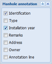
Click Manhole annotation to annotate a manhole. This annotation is created mainly as described in the chapter Creating an annotation. The settings available for manhole annotations are as follows:
- Identification: Manhole identifier
- Type: Manhole type
- Installation year: Manhole’s installation year
- Remarks: Comments related to the manhole
- Address: Manhole’s address
- Owner: Owner of the manhole
- Annotation line: Select whether an annotation line is drawn
Pole annotations
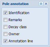
Click Pole annotation to annotate a pole. This annotation is created mainly as described in the chapter Creating an annotation. The settings available for pole annotations are the following:
- Identification: A combination of the pole’s line section identifier and pole number. If these are not defined, the identification information cannot be added to an annotation.
- Remarks: Comments related to the pole
- Decay class: Decay class of the pole
Owner of the pole
Annotation line: Select whether an annotation line is drawn
Point annotations
Click Point annotation to annotate a point object. This annotation is created mainly as described in the chapter Creating an annotation. The settings available for point annotations are the following:
- Identification: Identifier of the point object
- Distance: The distance represented by the point object (e.g. for a milestone)
- Length: The length represented by the point object
- Description: The description of the point object
- Annotation line: Select whether an annotation line is drawn

Diagram removal tool
- In the Annotations menu, select Diagram removal tool
 .
. - To remove a diagram, click its area on the map.
- If you want to remove multiple diagrams, activate the Diagram removal tool separately for each diagram.