In the KeyNet toolbar, click Logical cross-section  to open the Logical cross-section form. You can also open this form through the telecom premises’ list of Devices or through the list of Telecom premises of the circuit section by clicking the right mouse button and selecting it in the displayed menu. The Logical cross-section form displays the connections between the connectors in the selected telecom premises and device and information on the related circuits. This form is also used for reserving a connector or sub-circuit for a circuit, for switching pairs, and for releasing a reservation.
The Logical cross-section form displays information on the selected telecom premises, such as identifier, name, type, usage state, address, ownership, and the devices on the telecom premises. The connectors and related connections of an activated device are listed in a separate section on the form.
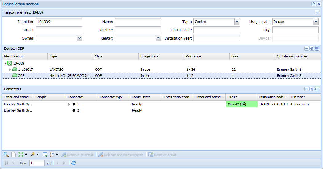
The Devices list includes information on the device, such as the device identifier, type, class, usage state, and pair range. The column named Free indicates how many connectors in the device in question are available. The OE telecom premises column displays the telecom premises that the device in question can access.
On the Devices list, click telecom premises or a device using the right mouse button. The displayed menu includes the following functions: Open telecom premises, Open in – Device form, Open in – Telecom premises device list, Print crossreport, Expand/Collapse, Edit connectors, Circuits, and Update logical connections.
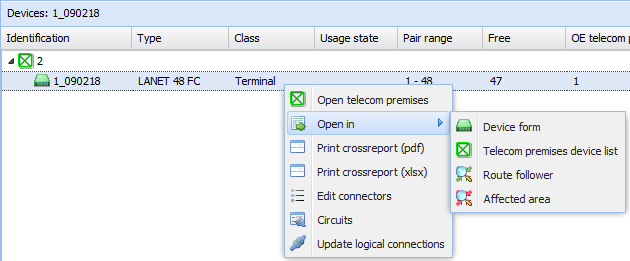
Click Open telecom premises to open the Telecom premises form for the telecom premises in question.
Click Open in – Device form to open the Device  form that includes the information on the selected device.
Click Open in – Telecom premises device list to open the Devices tab of the Telecom premises form and to view information on the selected device.
Click Open in – Route follower to open the Route follower form with information on the telecom premises in question.
Click Open in – Affected area to open the Route follower form pre-completed with the selected device’s connectors and cables connected to the connectors. The route follower highlights the connection routes that are connected to the selected device either directly or over logical cross-connections.
Click Print crossreport to create an Excel or PDF report on the connectors and connections of the selected device.
Expand/collapse opens/closes the devices in the device’s sub-hierarchy.
Click Edit connectors to open the Connectors for device form, on which you can name and edit the connectors of the device.
Click Circuits to open the Circuit list of a device’s connections.
Click Update logical connections to create or update a device’s logical connections.
The columns in the Connectors list may include the following:
Other end connector | The connector to which the viewed connector has a logical connection. Telecom premises/device/connector. |
Length | The total length between the connectors. |
Connector | The name of the connector. |
Connector type | The abbreviation of the connector type. |
Const. state | The construction state of the connector. If the construction state is not built, it is not shown on the connector list. |
Cross connection | The connector to which the connector of the row viewed has a cross-connection. Displayed as: device/connector. |
Other end connector | The other end connector of the cross-connection. Displayed as: telecom premises/device/connector. |
Circuit | The circuit that has been reserved for the connector. Displayed as: circuit (abbreviation of the usage state). |
Installation address | The street name and number of the customer’s installation address (the address of the starting point is used by default, and the selection between the starting/ending point can be defined in the database). |
Customer | The name of the customer linked to the circuit. Access to the Customer form. |
Connector number | The connector number (column hidden by default) |
Owner | The name of the circuit’s owner. Access to the Customer form (column hidden by default) |
Comments | Additional free-form details related to the connector (column hidden by default) |
Installation address (2nd) | Secondary installation address (column hidden by default) |
The colours on the connection list of the logical cross-section form indicate the usage state of the connector in question:
In use |
Pre-connected |
Partially pre-connected |
Soon in use, Soon free |
Free |
Ready to be connected is used if the TTMi interface is in use.
Search functions on the Logical cross-section form
There are several options for opening telecom premises on a form, such as using its identifier, using the Pick from map tool, or clicking Pick from telecom premises form
  . The available search criteria include all the fields of the telecom premises form, and search criteria can be entered in full or partially with % as the wildcard character.
You can also retrieve telecom premises based on the device identifier. Use the Device field to retrieve to the Logical cross-section form all the telecom premises that include the device identifier entered as a search criterion. The Device field is active when the form is empty, or when you click Clear  .
.
Compare logical cross sections
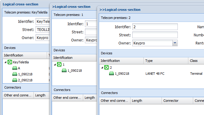
You can view several different logical cross-sections at the same time by using the Compare logical cross-sections  tool. This tool enables simultaneous comparisons such as comparisons between various devices, their connectors, and circuits in some specific telecom premises. The logical cross-section from which the Compare logical cross- sections function is activated will become a so-called primary form, and the Logical cross-section forms used for comparison will be named in accordance with the header >Logical cross-section.
Changing logical reservations for connectors
On the Logical cross-section form, you can change the circuit reserved for a device’s connector, or you can change the circuits to go through the same device’s other connector that has no circuits.
On the form, select the connector with a circuit or circuits. Alternatively, you can also select an individual circuit row by opening the connector’s circuits for viewing.
Then, click  Reservation change in the menu displayed when you click the right mouse button. Except for the Connectors section, all other sections on the Logical cross-section form will be disabled.
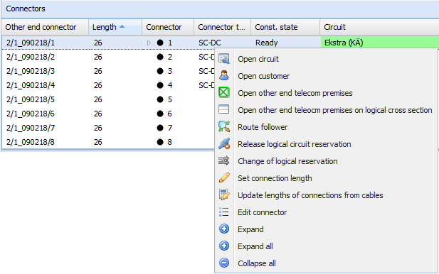
Next, in the same device, select a connector that has no reservations. Click the right mouse button and select either Accept reservation change or Cancel reservation change. Select Route follower to check the route.

Releasing a connector reservation
To start the release of a circuit reservation, select the reserved connector on the list and click Release circuit reservation  in the tool bar at the bottom of the form. You can also activate this function by clicking a connector with the right mouse button (Release logical circuit reservation).
You will see the following question: Are you sure you want to release the circuit´s reservation? If you answer Yes, the reservations for the selected connector and connection will be removed from the circuit in question.
Filtering devices
In the top-right corner of the Devices section, click Device filter  . Filter devices based on name, type, class, usage state, other end, service and connector. Select or enter the filters and click Update to view the filtered devices on the Devices list.
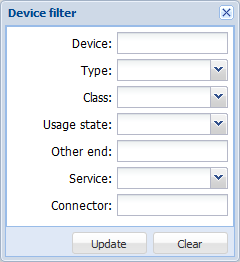
When devices are filtered, the form functions are applied to a limited group of devices.
In the top-right corner of the Devices section, click Clear device filter  to remove filters.
Filtering connectors
In the top-right corner of the Connectors section, click Connector filter  . Filter connectors based on the other end, length, connector, connector range, connector type, service, construction state, owner, remarks, circuit, customer, usage state, and installation address. To view only connectors that are not reserved for circuits, select the Free only checkbox. Select or enter the filters and click Update to view the filtered connectors on the Connectors list.
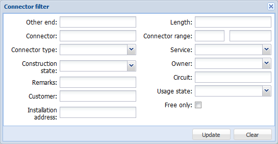
When devices are filtered, the form functions are applied to a limited group of devices.
In the top-right corner of the Connectors section, click Clear connector filter  to remove filters.
Editing connectors
You can open the Connector form for editing from the Logical cross-section form or Telecom premises form. More information on editing connectors is provided in the chapter Managing connectors.
Click the right mouse button and select in the context menu  Edit connectors either in the Devices section (the connectors of all devices on the telecom premises or all the connectors of a device) or in the Connectors section (individual connectors). To activate the numbering of connectors in the view, go to the drop-down menu for Columns and select Number. The connector number column is hidden by default.
Connector splitting
- In the Connectors section, select the connector you want to split. Note that you cannot split a reserved connector.
- In the context menu, select
 Connector splitting.
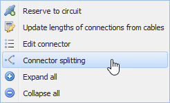
- Select the type of the new connector in the drop-down menu for Connector type.

TIP: If no suitable connectors can be found in the database, check that the connector type has been defined for the connector you selected. More information on defining connector types is provided in the chapter Editing connectors.

Click Split to split the connector.
Updating lengths of connections
Define the length of a connection by choosing  Set connection length in the context menu, while the mouse pointer is positioned over the required connector.

 Use the Update lengths of connections from cables function to update the lengths of all logical connections based on the actual cable lengths.
