Default values can be defined for most objects, and users can use these values as the basis for creating a new object. See Default form values.
Managing settings defined by an admin user
Admin users can save default values for an object by clicking Save as default in the menu for Save  . The defaults are then available to all users. The Save as default function is only displayed for admin users, and it is active when a form has been cleared or an unsaved object is open on the form.
Managing settings defined by a user
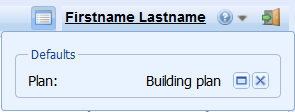
On the Plan form, you can define the object in question as the default for the duration of the session. Click  to do this. After this, in addition to other default settings, the Plan field will be filled in on various forms, when you click Defaults
  . Refer to the section Set as default plan for more information.
The defined defaults are displayed in the Defaults  dialogue box in the top-right corner of the screen.
Click Show on the form  to open the default object on its own form. Click
  to remove the default setting.
TIP: If there is no Defaults  button in the top-right corner, the user has no active default settings.
NETWORK FOLLOWER
The Network follower  tool can be found in the KeyAqua
  tools. This function lets you follow a water and sewer network, its connections, and elevation data (in sewage and rainwater networks). Network following requires ducts and nodes to be connected to each other in KeyAqua. On the form, use route options to specify the direction of following and whether the network will be followed across open valves or not.
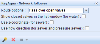
Route options: Continue over open valves
Following will continue over the valve if its status is not Closed. The network will be followed across the open valves for as long as possible.
Route options: Stop on valve
Following will end at the first valve that is found. When following in both directions, following will end at the first valve found in each direction. The network section between the valves will be highlighted on the map.
Show closed valves in the list window (for water):
When network following ends, a list of all closed valves for which following ended will be displayed.
Use z-coordinate (for sewer):
The network will be followed downhill using the duct route and in accordance with the sewer duct’s z-coordinates. This option is not available for water ducts.
Use flow direction (for sewer and pressure sewer):
The network will be followed downhill along a sewer or pressure sewer duct in accordance with the flow direction settings. The flow direction for ducts can be defined to be different from the elevation-based flow direction.
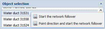
Network following is started from either a node or a duct. The network object from which following will be started is selected with the Network follower  function. Select the duct or valve you want by defining an area on the map with the left mouse button. A list of the found objects will be displayed. To start following, place the mouser cursor on the selected object, click the right mouse button, and select Start the network follower. The network will then be followed in both directions. If you select a water duct, you can indicate the direction in which the network will be followed on the map. To do this, click Point direction and start the network follower. The followed network will be highlighted on the map. To stop following, click Remove map layer
  or close the Network follower form.
For water ducts, you can either choose to follow in both directions or indicate the direction in which the network will be followed.
The results for network following can be listed or shown in a group display, through which you can, for example, select the consumer points affected by an interruption in water supply and send an SMS to the customers. To use these functions, click List  or its drop-down menu.
CCTV
The CCTV form is used to define the CCTV results that are displayed on the map. The CCTV results imported in the system can be visualized on the map with the CCTV  function in the KeyAqua
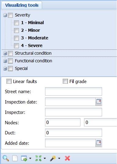
  tools. On the CCTV form, select the severity levels that you want to visualize. In addition, select the required structural and functional conditions and special observations. To include all severity categories, select the Severity checkbox. Descriptions can be searched, for example, by street name, inspection date, or inspector.
Click Show  to center the map on items that meet the street name and/or inspection date criteria. If these have not been specified, the software will retrieve CCTV data from the displayed area. Click Clear
  to clear the selections you have made, and any objects visualized on the map. You will then be able to make new selections.
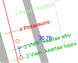
The required objects of CCTV inspections will be visualized on the map as text and color. The number in front of the text and the colour of the text indicate the severity level: light green indicates severity level 1 (minimal defect), whereas red indicates severity level 4 (severe defect).
Illustrating objects:
- At the top of the form, select the severity levels whose defects you want to illustrate on the map.
- Choose which type of defects or special observations you want to illustrate. If you want to include all severity levels, you don't have to select each one separately, but by selecting Severity checkbox, all will be selected.
The fields at the bottom of the form can be used as search factors when searching for information of inspection. The inspection can be searched for example by street name, the inspection date or inspector’s name. If you search by the name of the street, for example, all inspections are searched for which the name of the street in question is given as the target name. In this case, you can find several inspections made at different times. The inspection can be identified by the name of the street and the inspection date.
Searching inspection info
The search for CCTV inspection data is started from the Search  button at the bottom left of the toolbar.
When you search for CCTV inspection information by street name, inspection date or inspector’s (researcher) name, the search result will be the manhole of the CCTV inspection in question on the form. Form can be cleared with the Clear  button located in the toolbar.
Click Show  to center the map on objects that meet the street name and/or inspection date criteria. If these have not been specified, the software will retrieve CCTV data from the displayed area. The Show all button, which is activated from the drop-down menu of the Show button, illustrates all observations obtained in the search.
With the Locate  function and the Locate all function found behind the drop-down menu, the map is centered either on a single manhole or on the entire searched inspection.
With the Clear  button, both the selections made and possibly the objects illustrated on the map are lost, allowing new selections to be made.
The desired objects of CCTV are illustrated on the map with text. The number in front of the text and the color of the text indicate the degree of severity: light green reflects severity level 1 (minimal fault), red indicates severity 4 (severe fault).
Tabs related to CCTV on forms
For example, on the Attachments tab of the Sewer duct  form, you can upload still images related to CCTV inspections.
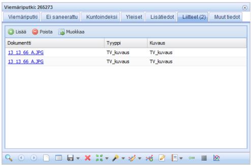
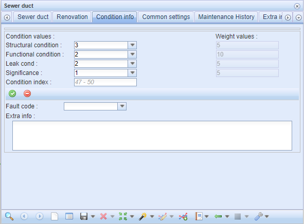
You can also document three additional condition values from the Condition info tab which are Structural condition, Functional condition, Leak cond. Necessary information must be given to these fields for the calculation of the Condition index by the system. The CCTV functionality must be activated on the form.