The Manhole form functions mainly in the same way as described for other point objects in the chapter Buttons on object forms.
Managing manhole connections
A manhole has physical connections and duct connections. Click Connections management to view and edit them. The Connections management form is displayed, on which you can view Duct connections. Duct connections are discussed in more detail in the chapter Duct connections management. In the Duct connections menu, you can also select Physical connections. More information on them is provided in the chapter Managing physical connections.
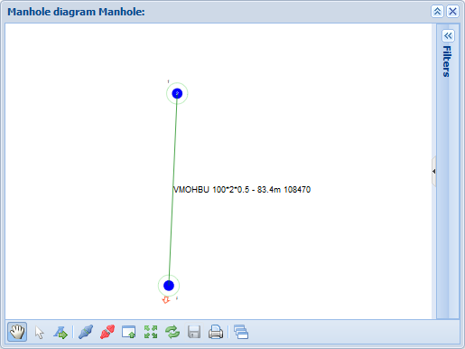
Manhole diagram
A manhole diagram illustrates the connections inside a manhole. In the drop-down menu for Tools , click Manhole diagram
 to open the manhole diagram. The manhole diagram illustrates the various network elements (manholes, splices, ducts) with colours and symbols.
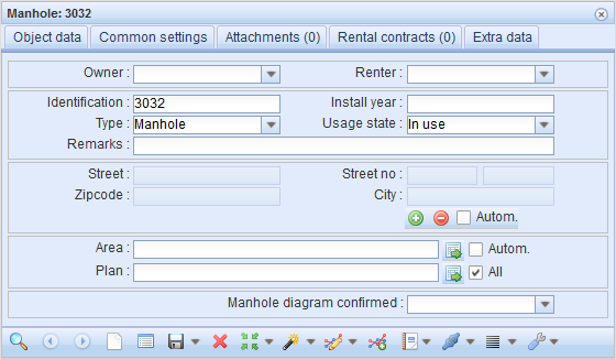
The Manhole form includes the field Manhole diagram confirmed. In the drop-down menu, select Yes/No according to the situation. If this field is empty, no actions have been taken regarding the manhole diagram related to this manhole.
Saving a manhole diagram
Click Save diagram  to save the diagram.
Locating and highlighting the objects of the diagram on the map
When your mouse pointer is positioned over an object, select Locate or Highlight
 in the context menu.
Viewing and editing the information on the diagram objects
When your mouse pointer is positioned over an object, select Edit (object) to open the form on a separate form. The general functions of the object forms have been described in the chapter Buttons on object forms.
Moving and rotating the objects of the manhole diagram
You can move and rotate the objects of the diagram by clicking Pick . Click
 to rotate, and move by grabbing the square over the object. Click Save diagram
 to save changes.
Printing a manhole diagram
Click Print to print the diagram. The diagram is then opened on a new tab/window in the browser, and the browser’s printing function is initiated. Follow the browser’s instructions to print. You might have to choose the printer and other print options and click OK.
Adding text to the manhole diagram
- Click Add text
 .
. - Enter your text in the Enter new text field that is displayed when you click on the diagram.
- Click OK.
- Position your text in the diagram.
- Click Save diagram
 to save changes.
Creating connections in a manhole diagram
- Click Connect
 .
. - In the diagram, select the cable you want to connect.
- Select the splice you want to use for the connection.
- The following notification is displayed: Cable successfully connected to a manhole.
- Click Save diagram
 to save changes.
Disconnecting connections in a manhole diagram
- Click Disconnect
 .
. - In the diagram, select the cable you want to disconnect.
- You will be asked the following question: Are you sure you want to remove this connection? Select Yes.
- The system provides a notification that the cable connection to the splice has been disconnected, and has been connected to a manhole.
- Click Save diagram
 to save changes.
Importing a splice to a manhole diagram
- Click Import splice from form
 .
. - If the Splice
 form contains a splice, it will be imported to the manhole in the manhole diagram.
 - Add the splice to the desired location in the manhole diagram by clicking.
- If the Spliceform is empty, the system notifies you that there are no splices that can be imported.
- Click Save diagram
 to save changes.