Use the Survey file import  form to view the survey data in the system and to import survey files into the system. Surveys carried out in the field can be imported directly into the system.
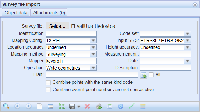
Importing a survey file
- In the main toolbar, click Survey file import
 .
. - Click Choose file to select the file for reading.
- Select the right Code set used in the survey file.
- Select the Mapping configuration that is appropriate for the survey file structure.
- Select the correct input SRSfor the survey file.
- KKJ (such as KKJ / Finland zone 1)
- Shortened GK (such as ETRS89 / ETRS-GK19FIN (EPSG:3126))
- Standard GK (2010) (such as ETRS89 / ETRS-GK19FIN 2010 (EPSG:3873))
- local coordinate systems (such as ANC Finland)
- WGS (such as WGS84 (EPSG:4326))
- Select Operation:
- Also create objects: If you select Also create objects, the mapped ducts, manholes, valves, and so on, are created on the map.
- Write geometries: The survey geometries include point and line objects, and the Surveys layer is activated in the Layer selection when these are applied.
- Select the Combine points with the same kind code checkbox to form lines based on consecutive points.
- Select the Combine even if point numbers are not consecutive checkbox to join lines with non-consecutive point numbers.
- Fill in the rest of the fields as necessary.
- Click Convert
 in the form’s toolbar. The survey file is automatically saved after the conversion.
Any errors and warnings are displayed on the list. Usually, these errors are related to the structure of the survey file, and they are displayed to help find the possible errors in the file.
Survey results
Click Show results to view the survey objects in a list. In addition, the form will open automatically, for example, when you browse through the survey items, and the information on the form is updated in accordance with the survey that is being viewed.
The form shows what types of objects were documented in the imported survey. The list has seven columns by default: Type, Kind code, Code description, Geometry, Point number, Line number, and Length. The columns displayed depend on the survey setting that is applied. The objects for which KeyAqua network objects have already been created are displayed in the list with a green background.
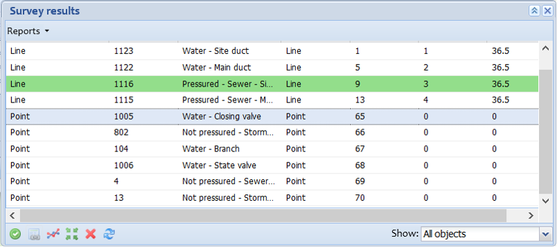
The imported survey file results can be located or deleted, or they can be used to create individual objects. Update the Results of the Survey list by clicking Refresh .
.
The Show menu includes the following options for displaying the Results of the Survey list: All objects, Created objects, and Not created objects.
Creating, locating, and deleting network objects
To create KeyAqua objects with the type defined in the Type column, select them on the list and click Create objects . The rows of created objects are marked in green.
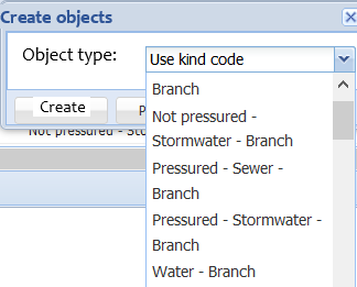
If you want to create different types of items on a map from survey objects, first hold down the Shift key and click the left mouse button to select similar items from the list (Line or Point). Then click Create objects and select the correct Object type in the Create objects window that opens. For line objects, water and sewer duct options are available, and types such as manhole and valve are available for point objects. Click Create to display the survey items on the map.
To locate a single survey geometry, select the correct object row and click Locate . To delete a single survey geometry, click Delete object
 when the geometry in question has been selected. The selected geometry will be displayed on the list in blue.
Editing network objects
- Select the created object (green) that you want to edit.
- In the toolbar at the bottom, select Edit
 , or click the right mouse button and select Edit in the menu.
 - The form for the created network object is displayed. For example, if the object’s type is Sewer duct, the object is opened on the Sewer duct form.
Editing the geometry of survey objects
You can view survey objects on the Survey Line string and Survey Point forms that are available in the menu for Survey file import . The main purpose of these forms is to provide tools for editing the location and geometry of the objects. You cannot use forms to create new survey objects.
- On the list, select the object whose geometry you want to edit.
- In the context menu, click Edit geometry
 , or select Edit geometry
 in the toolbar at the bottom.
 - Depending on the geometry type of the object, the Survey Point or Survey Line string form is displayed.
Survey results report
You can create an Excel report on the survey results, including the applicable codes, their number, and the total length per code. Create a report by clicking Survey results report in the menu for the Reports button.
Survey file description
Admin users can define various Survey settings for survey files.
Mapping configurations
Select the mapping configuration that is appropriate for the survey file structure. Coordinates can be in the order North-East-Height (PIH) or East-North-Height (IPH), this can be defined on Mapping Config field.
T3 PIH format
The so-called GT format T3 PIH 11 (Pohjoinen, Itä and Height) is discussed next. The GT file is a text file that consists of columns. Each row has 7 or 8 columns. These are called T1–T8. Columns are separated using space or tabulation characters. The data in a column must not include space or tabulation characters and, apart from column T2, the column cells cannot be empty.
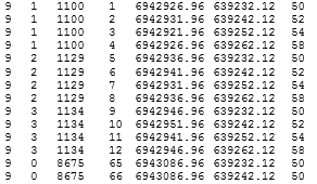
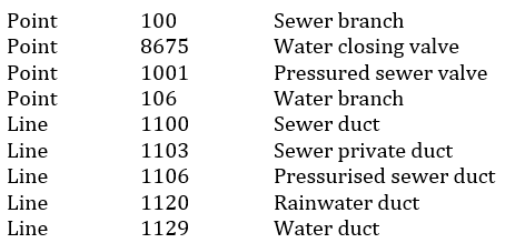
In the figure below, an example of a land survey file. The survey file includes a sewer duct (1100), two different types of water ducts (1129 and 1134), and two water duct shut-off valves (8675), as shown in the code set used on the next page.
TIP: PIH = North, East and Height
T8 data model:
The file has information on one coordinate point on each row. The first four numbers are the point identifiers T1...T4, and T3 is typically the survey code. Survey code refers to a “key” that is used to link the description and property values to a certain coordinate point. The applied code set defines the kind codes that are used in a land survey file. These can be edited via the admin user interface.
- T1 - Surface code: contains information about surface (for example ground, wetland, peatbog, unknown, etc.). If you are not sure, use “0”.
- T2 - Line code: is used to separate line object lines. For point objects, T2 is 0. If it's different number than zero – it is a line. The same number needs to appear for all vertices belonging to one line.
- T3 - Survey code: contains information about KeyAqua specific code of the object. With this KeyCom identifies what network object is created. The used Code set defines what kind codes are to be used when doing the land survey. The land survey code set can be modified from the admin interface.
- T4 - Point number: ID number of a surveyed point. The identifier T4 is usually the point number defining the order in which points have been measured.
- T5 - North coordinate: the north coordinate.
- T6 - East coordinate: the east coordinate.
- T7 - Height (Z): height from the sea level.
- T8 - Comments: comments related to survey point or line.
The following code set is applied to the example:
T3 PIH T11 format
The GT file is a text file that consists of the same eight columns as the T8 format and has additional three columns which are Depth, Location accuracy, Height accuracy and Depth accuracy. Each row has total of 11 columns. Columns are separated using space or tabulation characters. The data in a column must not include space or tabulation characters and, apart from column T12, the column cells cannot be empty.
T11 data model
- T1 - Surface code: contains information about surface (for example ground, wetland, peatbog, unknown, etc.). If you are not sure, use “0”.
- T2 - Line code: is used to separate line object lines. For point objects, T2 is 0. If it's different number than zero – it is a line. The same number needs to appear for all vertices belonging to one line.
- T3 - Survey code: contains information about KeyAqua specific code of the object. With this KeAqua identifies what network object is created. The used Code set defines what kind codes are to be used when doing the land survey. The land survey code set can be modified from the admin interface.
- T4 - Point number: ID number of a surveyed point. The identifier T4 is usually the point number defining the order in which points have been measured.
- T5 - North coordinate: the north coordinate.
- T6 - East coordinate: the east coordinate.
- T7 - Height (Z): height from the sea level.
- T8 - Depth (from the ground level or from the open trench): the depth value is always entered by the surveyor based on how deep the cable is from ground level. Whether measurement is taken from ground surface or from an open ditch it does not affect the depth value.
- T9 - Location accuracy: according to the measuring device, to 2 decimal places.
- T10 - Height accuracy: according to the measuring device, to 2 decimal places.
- T11 -Depth accuracy: if an exact value cannot be interpreted for a measurement point in a survey mapping situation, the accuracy value of the depth must be inserted. The value is in meters, e.g., 1.0; the value can be zero; the field must not be empty.
- T12 - Comments: comments related to survey point or line.