All object forms used for managing objects and events have the same structure and functions. Only the information included on the object forms varies somewhat depending on the object form. For this reason, each object form can only be used for managing the specific object related to the object form, for example, the Splice form is used for splices and the Telecom premises form is used for telecom premises.
The functions of the buttons displayed at the bottom of object forms are always the same even though the information content of the forms may vary. In other words, the buttons always function in the same way for all network objects and on all forms. The buttons that are displayed depend on the user’s privileges. For example, read-only users cannot update information. If the button is dimmed, it is not available. The button functions are introduced in the next chapters.

In addition to the buttons displayed on an object form, some object forms contain additional functions that are used in the same way on all forms. Additional functions are used, for example, for adding dates or address information. These functions are discussed in the chapters Entering a date and Managing address and apartment information on object forms. The functions of buttons that are not introduced in this Chapter are discussed in connection with the relevant object forms.
Favorite tools
Click Favorite  in the top-right corner of the form to define the form in question as a favorite. User-defined favorites are displayed in the toolbar at the bottom of the map view, from where you can open them quickly. Future version updates may affect your settings concerning your favorites.
You can also save the form’s search results as favorites:
- Retrieve the required information to the form, as instructed in the Retrieving information to a form and Picking objects from the map chapters.
- Click the Favorite button.
- You can enter a name for the search results in the Save new search dialogue box.
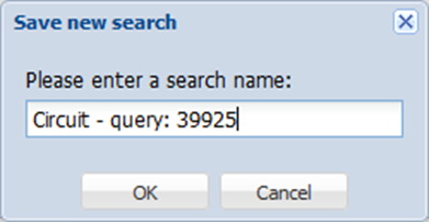
- Click OK.
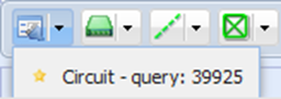
- Your search results are now saved in the Favorites toolbar.
Deleting favorites:
Clear the form that you want to remove from your favorites. Click the Favorites button at the top. The program will ask you to confirm the deletion of the favorite.
OR:
Right-click the favorite in the bar at the bottom. The program will ask you to confirm the deletion of the favorite.
Note! By deleting the favorite, you delete the search result queries associated with the favorite.
Retrieving information to a form
To retrieve data on all objects to the form, first click  to clear the form and then click Search
 . If you want to retrieve data on some specific object types, you can define the search criteria that are applied to your search. For example, if you want to find information on all telecom premises that are located on Bramley Street, enter Bramley Street in the Address field on the Telecom premises form and click Search. The number of search results is displayed in the bottom left corner of the object form. If there is more than one result, you can browse through them with the arrows
 . You can enter values in any fields on the form or use a combination of fields to search for objects. If you want to browse through a large number of search results and update information related to some individual search result, the easiest way to do this is to use the List
 function. This function is discussed in more detail in the chapter List view.
TIP: You can use % as a wildcard character to substitute text when carrying out a search. For example, instead of Bramley Street, enter Braml% in the Address field to include all addresses starting with Braml in the search results. If you enter the character ! in a field, the search returns objects with no information in that specific field.
There is an Identification field on each object form. Identification refers to the ID of each object. These IDs are automatically generated for each new object. Users can also choose to enter an ID manually. You can use Identification as a search criterion when you search an object.
Selecting multiple items
Some forms provide the option to select multiple items for searching. For example, the Plan form allows searching for multiple items based on values defined in the Type field. Hold the Ctrl key down and use the right mouse button to select the values in the Type field menu that you want to use as search criteria.
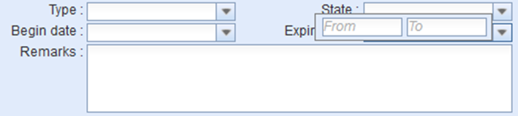
Searching by a date or number range
On some forms, you can search by a date or number range by double-clicking the field for a date or numeric value. When this function is activated, the original date field (or the field for a numeric value) is replaced with two new fields: the start and end values. Enter the relevant search criteria in these fields. When you click Search on the object form, all objects with their date (or numeric value) within the entered start and end values (including the entered values) are returned as search results.
Clearing an object form’s fields
You can clear the data in object form fields by clicking Clear  . This function clears the data in the fields, but it does not delete the data from the system. Clear the object form fields before conducting a new search, for example. When you click Clear, data on all searched objects for that form is deleted, not only the data related to the object that was displayed on the form. Any highlighting on the map is also removed.
Default form values
You can view the default values for the object form fields by clicking Defaults  . Values are displayed if they have been entered in the system. Default values can include, for example, the most common property data for an object. Admin users can modify default values. When you add a new object, you can use the Default
  function to speed up the process of entering property values. You can also apply default values when you search a database.
Updating object data
You can edit an object’s information on the form and update the information by clicking Save form  . For example, if you want to modify the usage state of some telecom premises and add information about the installation year, take the following steps: Open the required telecom premises on the Telecom premises form, go to the Usage state menu, and select In use. Then enter e.g. 2019 in the Install year field. Click Save
  .
.
Copying an object as a new object
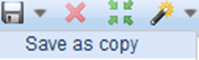
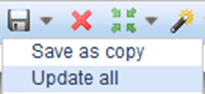
You can copy an object with the Save as copy function. This function creates a new object by using the same property values and location. We recommend using this function, for example, when the intention is to digitize several similar objects in the same place. The Save as copy function is available in the drop-down menu for Save .
Mass update (Update all)
With Mass update, you can update data for multiple objects at one go. This function is useful in many situations when multiple objects need to be modified simultaneously. The Update all function is available in the drop-down menu for Save .
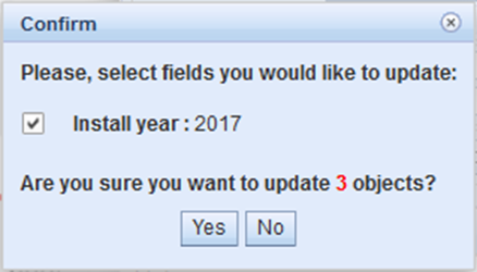
For example, if you want to update the year 2016 as the installation year for all cables in the area, first retrieve information on all the cables in the area (area search) and enter 2016 as the value in the Install year field. Then, in the drop-down menu for Save form, click Update all. On the Confirm form, select the information that is to be updated for the objects if you have modified more than one form field.
Mass update of addresses
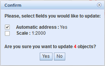
On the Telecom premises, Manhole, and Splice forms, you can update addresses to match the nearest address in the search results. First, in the Address section, select the Autom. checkbox, then go to the drop-down menu for Save form  and click Update all. The program asks you to confirm the fields that are updated. Click Yes to accept changes. You can do this, for example, in order to update incorrect or incomplete addresses of telecom premises.
Deleting objects and mass deletion
To delete objects from the system, retrieve an object through the form and click Delete  to open the Confirm dialogue box. The following dialogue box is displayed: Are you sure you want to delete this object? Click Yes to delete the object. This deletes both the property and location data of the object from the system. In other words, the object is no longer visible on the map and its information is deleted from the database.
You can find an object for deletion by defining search criteria and by clicking Search  if you have knowledge of some key property value, such as Identification. If you know the location of the object, you can pick the object data from the map with the Pick
  function.
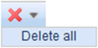
A Delete all function used by a specific user group may be available to you. This function is form-specific, and you can use it to delete more than one object at the same time. The Delete all tool is available in the drop-down menu for Delete. Delete all is available for objects that have no related circuit reservations or dependencies to other KeyCom objects that would cause problems at the database level. The Delete all function will notify the user if an object group includes objects that cannot be deleted.
Locating and highlighting an object
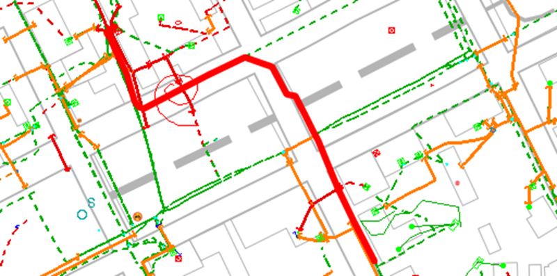
Objects on the form can be located on the map by clicking Locate  . The map is centered on the object that is highlighted on the map. Objects can be located if an object’s geometry has been stored in the system and it is within the permitted coordinates.
In the example figure, a cable is highlighted on the map.
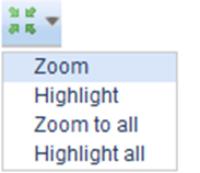
The drop-down menu for Locate also includes the following options: Zoom, Highlight, Zoom to all, Highlight all. These functions are introduced next.
- The Zoom selection centers the map on the active object on the form. (Displayed only for objects that have a location.)
- The Highlight selection highlights the active object on the map, but the map view does not change. (Displayed only for objects that have a location.)
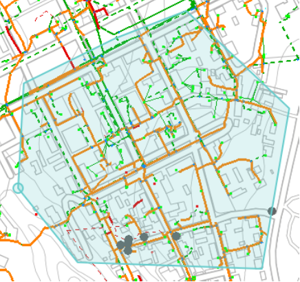
- The Zoom to all selection centers the map so that all objects retrieved to the form fit the map view.
- The Highlight all selection highlights all objects downloaded on the form, without changing the map view.
Picking objects from the map
To pick objects from the map , first click Pick  and then use the left mouse button to point at the object. The object’s information is displayed on the form. You can only pick objects relevant for the form in question, that is, if you try to pick telecom premises to a form for splices, the following text is displayed at the bottom of the form: No matches found. If you are not sure which object is in question, you can use the Info
 tool to define the object and then open the correct form for that object from the list of results.
TIP: If you want to view the information related to an object whose type you do not know, you can use the Info tool. In the Info list that is displayed, click Edit to access the object’s form. The use of the Info tool is discussed in more detail in the Info tool chapter.
Area searches
You can also pick the data for multiple objects at once. Click Pick  . Use the left mouse button to point at the starting point and hold down the mouse button until you have marked the area you want by drawing a rectangular. When you release the left mouse button, the information in the selected area is displayed on the form.
You can also select an area using the functions available in the drop-down menu for Pick  . Map view area retrieves the information on all objects in the map view. You can use the Free area function to select the required free-form area by placing points in required locations using the left mouse button. End the area selection by first clicking the left mouse button and then the right one. The search area is the area within the points you marked on the map.
With the Existing area function, you can select a map area that has been created with the Area tool (Area, Plan, Service area, Exchange/Telecom area), in which case the search is carried out within the selected area.
If the object form fields are empty when the search is carried out, the search results will include all the objects for the form type. You can use search criteria to limit the search results. Enter the search criteria in the fields of the form and click Pick  . You can then select the Pick from map checkbox in the dialogue window that is displayed. Carry out a search as described above for area search functions.
For example, if you want to view the information on all cables installed in 2016 in a specific area, enter the search criteria on the Cable form, that is, enter 2016 in the Install year field. After you have defined the search area on the map, the number of search results is displayed in the bottom left corner of the object form. Use the arrow buttons  to browse through the search results.
Modifying the geometry of an object
You can modify the geometry of the object on the form, that is, you can edit its location and form by clicking Modify  . A Modifying dialogue is displayed, in which you can select various settings related to modifying the object’s geometry. Click Save form
  to update the modified geometry and other form fields.
Modification settings
In the settings for geometry, you can select the snapping point applied to a point that is moved while holding down the SHIFT key. Select Point for snapping if you want to move the point to the same location as some other point. Use Nearest if you want to position a point on top of the line of a line object, meaning the point moves to the nearest point on the nearest straight line.
Modifying the geometry of a line object
Line objects can be modified on the Cable, Conduit and Line forms. Select a line object on the map and open its form. Select Modify  to activate the function for modifying the geometry of the object. Alternatively, you can click on a line object on the map to use the Quick modify function.
Quick modify function of a line object
- Point at the required line object on the map and click the right mouse button while holding down the Control key. If the map object includes multiple objects, the Object selection window will be displayed. Click the required object with the right mouse button and select Modify
 .
. - Select the required options in the displayed Quick modify dialogue box.
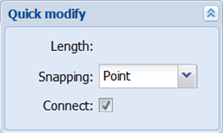
Drag the points highlighted in red to the required location or remove them with the Delete key. You can snap to another object by holding down the Shift key while releasing the left mouse button.
Click the right mouse button and click Save in the Confirm the move window to Save the changes. Cancel the changes by using the Cancel function.
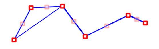
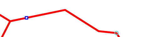
You can use the pink squares to add points. You can move the squares in the same way as the existing points. Position your mouse pointer over a square, grab it while holding the left mouse button down and relocate the square. When you release the left mouse button, the square becomes a new point. In addition, new pink squares appear on the line between the new and existing points. These can be used to create further new points.
Splitting a line object
Some line objects can be split by using the Split function. This function highlights the selected object on the map and displays the Splitting dialogue box. This dialogue box displays the lengths of the parts to be split. These lengths are automatically updated based on the selected splitting point. The Delete annotation selection is used to automatically remove from the map any annotations related to the object. If you select the Splice checkbox, a splice is automatically created to the point where the line object is split. The Split tool is displayed in the drop-down menu for Modify when an object can be split.
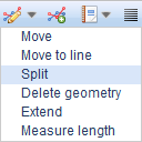
Select the point where you want to split the object and click the left mouse button to accept the split. Both objects created through splitting are now displayed on the form. Use the arrow buttons  to browse through the objects.
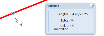
Extending a line object
A line object (cables, conduits) can be extended from the end that has not been connected. Activate this function in the drop-down menu for Modify . The Drawing options dialogue is also displayed. The functions of the Drawing options dialogue are described in the chapter Snapping and following (settings for drawing and modifying).
To continue the digitization of the object from its end point, create new points in required locations using the left mouse button. Create the end point of the object by first clicking the left mouse button and then the right mouse button. The object’s location and property values are automatically saved in the database.
Moving a line object to a line
You can move a line object to match the location of a linear geometry, cable, conduit or any other line object.
- In the drop-down menu for the Modify
 function on the form, select Move to line.
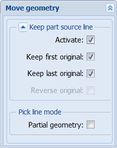
 - Select the required options in the displayed Move to linedialogue box:
- Activate: With this option, you can maintain a part of the line’s original location, while another part is moved to a new target line. Activate the additional functions for the line that is to be moved:
- Keep first original: Keeps the first part of the line unchanged up to the point where you click the line
- Keep last original: Keeps the last part of the line unchanged from the point where you click the line
- Reverse original: Reverses the order of the start and end points of the line to be moved
- Pick line mode: Partial geometry: You can choose a part of a route on both lines: the one you want to move and the target line
- With the left mouse button, point at the line to which you want to move an object.
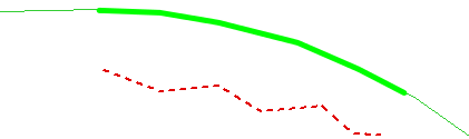
- Stop the line selection by clicking the right mouse button. The new location of the object to be moved is highlighted in green.
- Accept the object move by clicking Save or cancel the move by clicking on Clear.
Note! If you have selected functions that keep a part of the original line unchanged, the Reverse original function will not be activated before you have selected the start and end points for both the line to be moved and the target line.
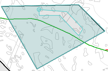
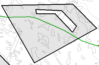
The Move to line function has been activated. The thin green line is the linear geometry. The thicker green line represents the new location of the object that is moved.
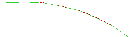
In the example figure below, the move has been accepted.
Moving a line object partially to a line
- In the drop-down menu for the Modify
 function on the form, select Move to line.
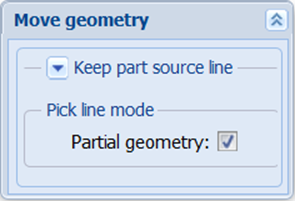
 - In the Move to line dialogue box, select the Partial geometry checkbox.
- Point at the map object (line, conduit, cable) to which the line is moved.
- Select the starting point on the target line.
- Select the end point on the target line.
- Repeat items 0–0 if you want the object to follow more than one line.
- Right-click to end the line selection. The new location of the object to be moved is highlighted in green.
- Accept the object’s move by clicking Save form on the form or reject it with the Clear button.
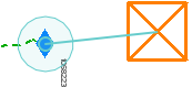
In the example figure, the starting point is displayed as a blue square, while the real-time location is displayed as a light blue circle.
Mass movement of line objects
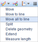
In the drop-down menu for the form’s Modify function, select Move all to line to activate a mass transfer. Note that more than one line object must be retrieved to the form to make mass movement possible. Take same actions as when moving a line object, as explained in the chapters Moving a line object to a line and Moving a line object partially to a line.
Moving a line object
You can move a line object on the map either freely by dragging it using the left mouse button or relatively by defining the distance from the original location.
In the drop-down menu for the Modify function on the form, select Move. The object is highlighted on the map and a Move dialogue box is displayed, in which you can select the Mode of movement.
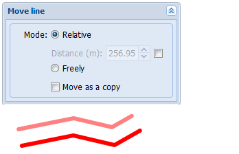
Select Relative to move an object horizontally or vertically for the number of metres displayed in the Distance field. Click the left mouse button to accept the location, and click Save form to save it.
Select Freely to move an object by positioning your mouse pointer over the red square and move the object to a new location while holding down the left mouse button. Release the left mouse button. Click Save form on the form to save the new location information.
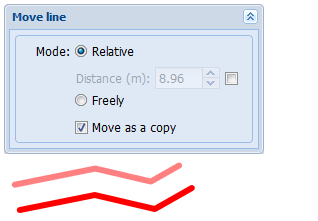
Selecting the Move as a copy checkbox makes it possible to copy the object to a new location.
Measuring the length of a line object
Use the Measure length tool to measure line objects. For example, if a fault occurs, you can use the Measure length tool to measure the length of a cable on the map.
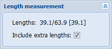
In the drop-down menu for the Modify  function on the Cable or Conduit form, select Measure length to activate the tool. Start measuring by following the line object using your mouse. Click the right mouse button to stop measuring. The first figure displayed after Lengths is the length from the start of the cable, and the second one is the remaining length to the end of the cable (39.1/63.9 in the example figure). The figure in square brackets refers to the cable reading. When the Include extra lengths checkbox is selected, the measurements will also include any loops/coils and their lengths.
TIP: You can use the Length measurement function to add an annotation for an object: Click the line object and position the annotation by using the left mouse button. Further information on adding annotations is included in the chapter Annotations.
Modifying the geometry of a point object
Modifying the location of a point object, such as a pole, is carried out in the same way as for line objects, the only difference being that there is only one point. Click Modify to have modified object be highlighted in red on the map. When you position your mouse over the object, the mouse pointer changes from an arrow to a cross. Click the object with the left mouse button and hold the button down while moving the object to a new location. Release the mouse button. Click Save form
 to save changes.
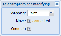
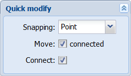
For some point objects, such as telecom premises, any objects connected to them can also be moved. The modification dialogue box for such objects includes a Move connected checkbox. If this Move connected checkbox is selected, any objects connected to the point object will also be moved. In addition, you can connect a point object, such as Telecom premises, when you make modifications.
The quick modify function of a point object
- Point at the required point object on the map and click the right mouse button while holding down the Control key. If the map object includes multiple objects, the Object selection window will be displayed. Click the required object with the right mouse button and select Modify
 .
. - Select the required options in the displayed Quick modify dialogue box.
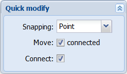
Drag the red square to the required location. You can snap to another object by holding down the Shift key while releasing the left mouse button.
Click the right mouse button and click Save in the Confirm the move window to Save the changes. Cancel the changes by using the Cancel function.
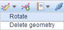
Rotating a point object
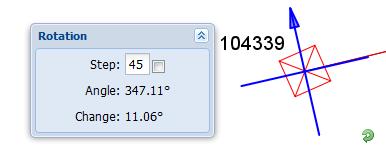
You can rotate the symbols of point objects (pole, telecom premises, point object, splice) on the map. You can select the rotation angle of an object by selecting Rotate. Click the Save form button to save the new rotation angle of the object.
When you click Rotate, a Rotation form is displayed. You can enter the required angle in the field on this form. You can use the form to define the steps as degrees. If Steps is selected, the rotation angle of the selected object changes in steps when you rotate the object. Angle displays the rotation angle of the object. You can rotate an object by grabbing the  symbol next to the object on the map. Click Save form on the form to accept the rotation angle. If you do not want the object to have a rotation angle, cancel it with the right mouse button.
Modifying the geometry of an area
You can modify the geometry of an Area (such as a Free area, Service area, Exchange/Telecom area) by clicking Modify  on the object form. The points of the area are highlighted, and they can be dragged using the left mouse button. To create a new point, click the dimmed square in the middle of a straight line and drag it to a new location. Click Save form
  to save changes.
Quick modify function of an area object
- Point at the required area object on the map and click the right mouse button while holding down the Control key. If the map object includes multiple objects, the Object selection window will be displayed. Click the required object with the right mouse button and select Modify
 .
. - Select the required options in the displayed Quick modify dialogue box.
Drag the points highlighted in red to the required location or remove them with the Delete key. You can snap to another object by holding down the Shift key while releasing the left mouse button.
- Click the right mouse button and click Save in the Confirm the move window to Save the changes. Cancel the changes by using the Pan
 function.
Digitizing a hole in an area object
- In the drop-down menu for Modify
 , select Make a hole.
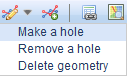
- Within the highlighted area, draw a hole that has the required shape.
When you stop drawing, the form is saved and the hole has been created.
Removing a hole in an area
- In the drop-down menu for Modify
 , select Remove a hole.
 - Click the hole you want to remove.
- Confirm the removal.
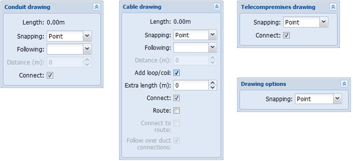
Deleting the geometry of an object
You can find the Delete geometry function in the drop-down menu next to Modify  . This function deletes the geometry of the selected object making the object disappear from the map. The property data for the object is not changed.
Creating a new object
Create a new object by defining its location, that is its geometry. Click Create  to do this. Always select the correct object form. For example, use the Conduit form to create a new conduit, and the Telecom premises form to create new telecom premises. You are usually required to provide at least some mandatory information on the form before you can create an object. You can add other object data either before or after creating a new object. Save the object data by clicking Save form
 .
.
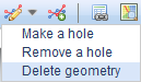
Click Create  to open the Drawing form, such as the Cable drawing form for creating a new cable. This form lets you define various settings related to drawing an object. The drawing settings of both point objects and line objects include Snapping, and you can choose whether the object you create snaps to another object’s point or the nearest point. The settings for line objects also include Follow. You can follow either Completely or Partially. Further information on following and snapping to objects is available in the Snapping and following (settings for drawing and modifying) chapter. The settings for Drawing vary, depending on the object that is drawn. In general, line objects have more setting options than point objects.
Creating a new line object
The drawing settings for line objects include the option Following. You can use this function, for example, when you digitize a cable to go through a conduit. When you have selected the option Completely for Following, point at the starting point of the conduit to have the line object you create follow through all the points of the conduit and to continue digitization from the ending point of the conduit. However, if you want to follow the conduit only partly, you can select the Following option Partially. This lets you follow the conduit to the required point, after which you can continue digitizing freely. If you want to follow an object in parallel within a specific distance, define Distance in the drawing settings. You can also add loops/coils with defined lengths and measure the length of the cable. Cable lengths are discussed in more detail in the Cable length, extra length and total length chapter.
Start creating the geometry of a line object by clicking the required starting point on the map using the left mouse button. Next, digitize the required points one by one by clicking the left mouse button at the relevant locations. Finally, end the digitization by first clicking the left mouse button and then the right mouse button. The object’s location and property values are automatically saved in the database. You can select the Connect checkbox, for example, to automatically connect a cable to a manhole. Connecting a cable to a manhole has been discussed in the chapter KeyCom object forms, in the section Cable connections.

The new cable can be connected to telecom premises or a splice already when the cable is created. When you digitize a cable, you use the so-called Snapping function, that is, hold the SHIFT key down while clicking the left mouse button over telecom premises or a splice. This makes it possible to connect the cable to the object, and a text is displayed at the bottom of the display: Snapping completed. If a text Snapping – not snapped is displayed at the bottom of the display, you have tried to connect the cable to an object it cannot be connected to. If a cable is created to an existing conduit, you can also snap to the points of the conduit. In this case, the conduit and cable are located in exactly the same place. When the Snapping function is active, the mouse pointer on the map is displayed as a light-blue circle. End digitizing the cable by first clicking the left mouse button and then the right mouse button at the location where the cable ends. The cable’s location and property values are saved in the database.
Creating a new point object
Create a new point object by clicking the left mouse button at the required location on the map. The program automatically saves the geometry of the object in the database. If saving succeeds, the following text is displayed at the bottom of the object form: Saved successfully. The object’s location and property values were saved in the database. The rotation function for a point object is activated immediately after the object has been created. A blue compass symbol appears over the object, indicating the rotation angle of the object. If you want to modify the object’s rotation angle, grab the  symbol using the left mouse button and rotate it to the required angle.
An object can also be placed on the map based on coordinates. First, deselect the Coordinate reading on/off checkbox in the bottom right corner of the map view and enter the coordinates for the required location. Then, click the  button to create a new object on the map in the desired location. Save form.
Creating new objects by using existing objects
You can create new objects based on the location of and information on existing objects:
Retrieve an object’s information to the form, for example, by picking an object from the map. After this, either
- click Create
 to create a new object based on the object information retrieved to the form. The program calculates the length of a line object based on the geometry of the new object.
OR
- In the drop-down menu for Save form
 , click Save as copy. A copy of the active object is saved on top of the existing object. This is a useful function, for example, when the same location is used for saving several cables.
Related tasks
An object may have related tasks. Check the status of tasks by positioning your mouse pointer over Tasks . The tooltip indicates the number of tasks and the number of unfinished tasks.
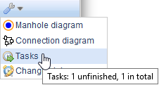
You can check the task status using the tooltip for Tasks . This button is included either in the toolbar or in the menu for the Tools button.
Adding a task for an object
- Open the task list for an object by clicking Tasks
 .
. - Click
 Add task to open the Task form with the Parent object information pre-completed on the form.
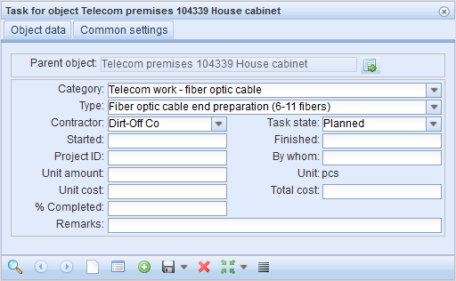
- Fill in the form fields. Type, Task state, and Unit amount are mandatory fields.
- Click Save form
 on the object form to save tasks. The task list for the object is updated with the new task.
The Task form is discussed in the chapter Tasks.
List
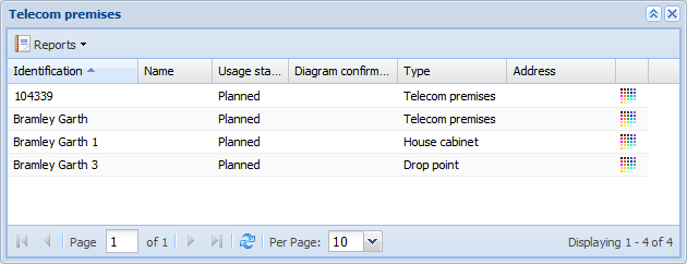
Many object forms include a List button. You can use it to view the search result objects in a list view. You can use this function to quickly browse through objects. The number of objects displayed on one page can be modified using the Per page selection. Use the arrow buttons to navigate the pages.
To view the tools related to the list, position your mouse pointer over the header field of a column. This displays a drop-down menu for the selected field  .
.
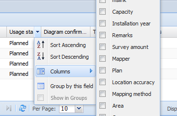
The menu includes an option for sorting the list based on the selected field either in ascending or descending order. The Columns function lets you select the columns that are displayed in the list view. The lists include the typical information for the object type as default data. The Group by this field function groups the list contents based on the selected field. The grouping can be cancelled by deselecting the Show in groups checkbox in the drop-down menu.
You can open a listed object displayed on the form by clicking the object with the right mouse button and selecting Edit selected.
You can use the Reports function to create reports on the listed objects. The report includes the same information as the list.
Show in group display
In the drop-down menu for List , select Show in group display to move the current search results from the form to a group display. Group displays are discussed in more detail in the chapter Group display.
Intersected properties
You can list the intersected properties for a network element or an area by selecting Intersected properties on the List menu. The displayed list includes information on the property IDs and any comments related to the intersected properties. You can also list all intersected properties for network elements or an area by selecting Intersected properties for all in the List
 menu. In this case, multiple objects or areas must have been retrieved to the form.
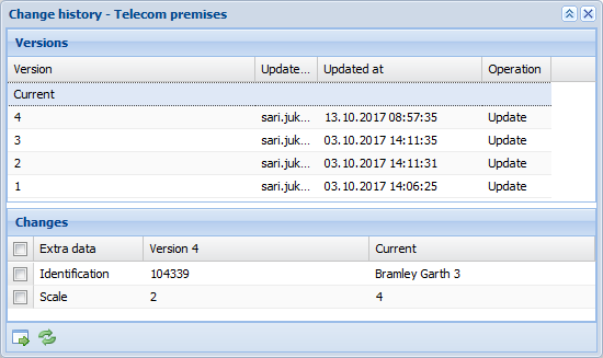
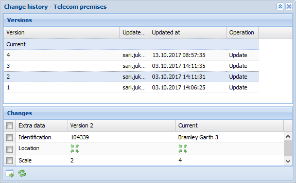
Change history
To view the change history of the object on the form, select Change history in the drop-down menu for Tools. The top section of the displayed form lists the various object versions, while the bottom section displays the changes made to the selected version.
In the figure below, a point object used as an example.
Restoring the values of an object
- In the Versions section, select the row that you want to restore.
- In the Changes section, select the checkboxes for the rows that you want to restore.
- Click Restore
 to update the selected information on the object form.
 - Click Save form
 on the object form to confirm the changes.
Comparing object versions
In the Versions list, select the rows for comparison to see, in the Changes list, the current version in addition to the selected versions.
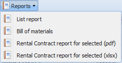
Reports from object forms
Reports can be created from forms, lists, and the main toolbar. Creating a report on objects that are included in a list of search results is discussed in the List chapter. The reports related to the main toolbar are discussed in the chapter Reports. Click Export
 to open the Reports menu for an object form.
You can create various types of reports in the system. The information on the search results displayed on the form is used to create a report.
For example, a Bill of Materials can be created from all object forms (cable, conduit, splice, pole, manhole, telecom premises, point object) based on data related to the search results displayed on the form. In addition, you can create reports based on the search results of the Info tool and from the Plan form.
In the drop-down menu for Export  , select Reports and click Bill of Materials to create a bill of materials. You can save the report as a file or open it directly in Excel.

Entering a date
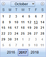
Many object forms include date as a property attribute that can be used, for example, to define when a survey was carried out. Adding a date has been standardised using a calendar, so that the same format is always used when dates are entered in the database. This makes it possible to search the database with date as a search criterion, as search results are then not incomplete due to dates entered in various formats.
Position the mouse cursor over the Date field and click the left mouse button to open the calendar window. The current date is selected as default. You can browse through months using the arrow buttons at the top of the calendar window. You can browse through years by clicking the year on the right or left. To select a date, click the correct day using the left mouse button. The calendar window is closed, and the selected date is displayed in the Date field.
Managing address and apartment information on object forms
To add address information on an object form, retrieve the information from the database or use the Autom. function. When addresses are retrieved from a database, addresses contain no spelling errors and they can be used as one search criterion.
Click Address on the object form to open the Address form. If an address has already been added for the object, the Address form displayed includes that address as a default address. If an address has not been added for the object, the Address form displayed contains no information. When you search for an address in the database, you can use the following search criteria: street name, number, postal code, or parts thereof with % used as a wildcard character. Click Search
 to start your search. The search function has been described in more detail in the chapter Adding an address in the database.
Use the arrow buttons to browse through the search results. When the correct address has been found, you can import it to the object form from which the Address form was opened. Click Update to form to do this. You can also locate an address on the map by clicking Locate
 to center the map on the address location.
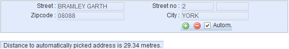
To enable automatic adding of an address, select the Autom. checkbox and click Save form. The nearest address is used and the distance to the nearest address is displayed at the bottom of the display.
Using the predictive search field
Some forms have a predictive search field that is used for connecting one object to another object, such as to an Area or a Plan.
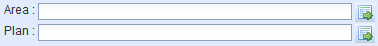
- Enter in the predictive search field at least the first three characters of a name/identifier.
- From the displayed search results, select an object or continue typing to limit the number of options.
If you do not know the name/identifier:
- Click Edit
 to open the object form.
 - Retrieve the correct object to the form by clicking Search or Pick
 .
. - When the correct object is displayed on the form, click Update to form
 .
.