The Cable  form can be used to create and modify cables that are created on the map. Colour codes for various cable types can be defined through an admin user’s user interface.
Creating a cable
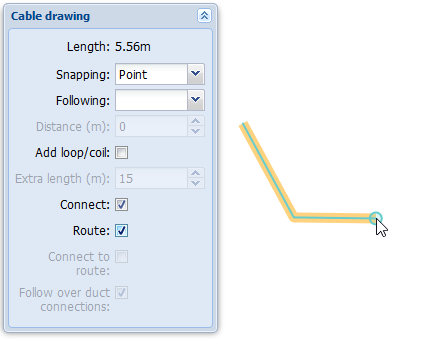
The cable creation process is very similar to the process of creating any line object. Open the Cable form. Click Create
 to open the Cable drawing form. The Following and Snapping functions are described in the Snapping and following (settings for drawing and modifying) chapter.
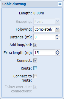
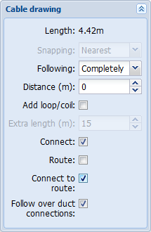
You can follow an existing line object at a distance you define. Activating the Following field activates the Distance field. In the Distance field, enter the distance between the new cable and the existing conduit or cable in metres. You can add a loop/coil on the cable’s route by activating the Add loop/coil checkbox. When you are drawing the cable, the program adds a loop/coil at the point you add if the Add loop/coil checkbox has been selected. Define the length of the loop/coil in the Extra length field. The figure entered in this field is included in the cable length. You can view the length of the line that you create in real-time in the Length field.
Related chapters: Automatic saving of a route when creating a cable and Connecting a cable to a route when creating a cable.
Cable connections
A cable’s connections to splices, manholes, and telecom premises are displayed at the bottom of the Cable  form . Cables can be connected to point objects from both ends or from one end only. If a cable is connected, information on the connected object is displayed in the menu. Otherwise, a Not connected text will be displayed. You can access the connections in the drop-down menu.
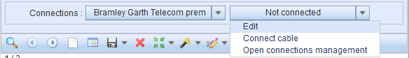
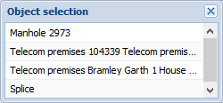
You can connect cables with the Connect cable selection. The software automatically searches for point objects within five metres of the start or end of the cable and opens the objects in the Object selection window. In addition, you can select the network element to be connected by defining an area on the map. If the defined area includes more than one object, an Object selection window will be displayed. Click a network element with the left mouse button to highlight the object on the map. This makes it easier to select the correct object. To create a connection, double-click or click the object with the right mouse button and then select Connect to cable. If the connection succeeds, the following text will be displayed on the form: Cable connected successfully, and the name of the network element is displayed in the Connections menu.
Click Disconnect cable to disconnect a connection. When this is successfully carried out, you can see the following text at the bottom of the form: Cable disconnected successfully. Select Edit to open the form for the object in question. You can then view its information or locate it on the map. Use the Open connections management to open the Connections management form, where you can view the object’s Physical and Logical connections. Connections are discussed in more detail in the chapter Connection management.
Cable length, extra length, and total length
The Cable form includes four fields that are related to the length of the cable: Length, Measure method, Start rdng(m), and End rdng(m).
There are three fields for Length:  The figure in the first field is the cable length that is derived either based on the map or the actual length of the cable. The second field displays the length of loops/coils added to the cable. The third field is the Total length field. It displays the combined length of the cable and extra lengths. If a safety margin for fiber-optic cable has been specified in the system (for example, 4%), it will be included in this field. The figures in the Length field are updated when a loop/coil is created using the Point object
 form, or when the length of a loop/coil in the cable is modified, or when the cable is edited on the Cable form by splitting or extending it.
In the drop-down menu for Measure method, select either From map or From cable. When you select From map, the system will automatically calculate the cable’s length on the map based on its points. The From cable method means that the user enters the cable’s length manually.
Measuring the length of a cable
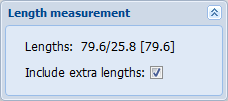
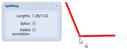
You can use the Measure length tool available in the Modify menu to measure the length of a cable on the map. This function can also be used to measure the distance to both ends of the line. For example, the figure below, Lenghts: Distance from the starting point of the cable/distance to the end of the cable [number of metres measured based on the location of the cable reel]. Select the Include extra lengths checkbox to include the lengths of loops/coils in the cable length.
You can add a Cable annotation with the Length measurement tool if you click the cable with the left mouse button. Annotation creation is discussed in more detail in the chapter Annotations.
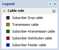
Cable role
You can define the role of a cable on the Cable form in the drop-down menu for Role. The default roles are: Drop, Transmission, Subscriber+Transmission, Distribution, and Feeder. The cable role has its own Thematics level. For more information on this, see the chapter Layers (Layer selection).
Cable occupancy
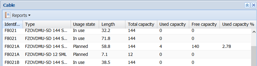
Cable occupancy (%) is based on the usage state of cable threads, construction state and information on its owner and the related right of use. Modelling the cable occupancy does not require separate physical circuit reservations. Click the List tool on a Cable form to view the cable occupancy for a cable. Add Used capacity as a column in the displayed view. You can also add total capacity and free capacity columns, which will provide more extensive information for the monitoring of the cable utilisation rate.
Columns in the cable list and settings for calculating the occupancy rate (defined through the KeyCom admin interface):
Total capacity provides information on the total number of cable threads.
Connected capacity is calculated based on information on the construction state of a thread and the owner or, alternatively, right of use.
Free capacity is based on the same information as connected capacity, but it also takes into account fiber threads with the usage state Free.
Used capacity is based on the same information as connected capacity, but it also takes into account fiber threads with the usage state In Use.
Used capacity % provides information on the percentage of connected threads in actual use.
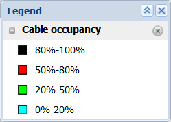
You can use the data on used cable capacity to create a map theme. In the sub-menu of Thematics, select Cable occupancy to highlight cables on the map in accordance with the colour defined for each occupancy category. Cable occupancy of conduit is another theme that can be used to highlight conduits and their cables in accordance with the used capacity.
Cable batch and cable ID information
You can use the Batch and Cable ID information to identify different cable delivery batches. If quality defects are discovered after cables have been installed, you can use this information to locate the cables in question.
Modifying the geometry of a cable
Modifying the geometry of line objects, such as conduits and cables, is discussed in the chapter Modifying the geometry of a line object.
Moving a cable
Cables are moved in the same way as other line objects. This function is described in more detail in the following chapters: Moving a line object, Moving a line object to a line, Moving a line object partially to a line and Mass move of line objects.
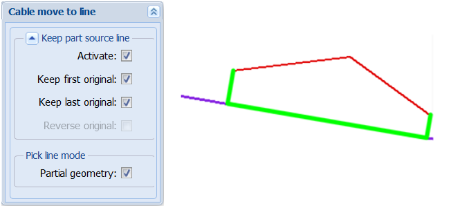
When you partially move a line object to a line, you can keep the cable ends at their original locations by selecting the Keep first original and Keep last original checkboxes in the dialogue box for Move to line. When moving partially to a line, select the start and end points of the cable to be moved, and then select the line to which you want to move the cable. You can also specify the route start and end points for the cable to which a cable is partially moved. Take the steps displayed in the bottom left corner of the map view.
In the example figure below, the user is moving a cable partially to a line while keeping the start and end points of the cable at their original locations.
Splitting a cable
Cable splitting is carried out in the same way as the splitting of other line objects. This function is discussed in more detail in the chapter Splitting a line object.
To add a splice when you split a cable, select the Splice checkbox in the dialogue box for Splitting. The cable threads are then automatically connected.
If you want to delete a cable annotation when you are splitting a cable, make sure the Delete annotation checkbox is selected.
Connecting a cable to a route when creating a cable
- Start the standard procedure to create a cable.
- In the drop-down menu for Following, select Completely.
- Select Connect to route. This activates the Follow over duct connections function, which means that the proposed routes cross duct connections.
- Snap to a conduit on the map. (See Snapping and following)
- In the displayed dialogue box Cable to conduit connection, select the conduit and/or one of its ducts.
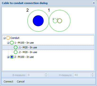
- Click Connect. When the Follow over duct connections checkbox is selected, and the route branches, select the route you want to follow from the list displayed.
- Continue drawing the cable or stop drawing. The cable is then saved.
Automatic saving of a route when creating a cable
When you are drawing a cable, you can automatically add a route that is appropriate for the cable location (e.g. a conduit).
In the Cable drawing dialogue box, select the Route dialogue box. When drawing a cable, a route will be created only for the section for which the Route checkbox is selected. If you deselect the Route checkbox while drawing, the route created up to that point is ended, and re-selecting the Route checkbox will start a new route. Routes and cables are saved when you stop drawing the cable.
The information applied to the route that is being created is obtained directly from the Conduit form. If the Conduit form includes no information, the default settings of the Conduit form are used.
In the example figure below, the created routes (conduits) are marked in orange in the figure. Cables are marked in blue.
A new cable is always automatically connected to the route drawn. If the route drawn is a conduit with a duct selected, the application places the drawn cable directly in the selected duct.
This function creates added value, for example, regarding planning. Based on the created routes, it is possible, for example, to calculate how many metres of ditch-digging is required for the plan. In addition, plan reports provide information on which cable is connected to which route, and it also provides the related length data (the Cable route metres).
In addition, for fiber-optic network plans, it is essential to be able to calculate how many metres of cable are required for the trunk network and the subscriber network (Cable role).
Cable tools
The bottom section of the Cable form includes a Tools button, with various KeyCom functions available in its drop-down menu.
Customers: Opens the Cable customers list. More information is provided in the chapter Cable customers.
Network diagram: Opens the Fiber/pair options dialogue box, in which you can select the information you want to include in the diagram. Click OK to open a Diagram form on which the pairs/fibers you selected are displayed. More information is provided in the chapter Diagrams.
Tree diagram: Opens the Tree diagram options dialogue box, in which you can select the fiber or pair range for the diagram. A Tree diagram includes the cable connections followed either completely or partially for a selected connector/pair range. More information is provided in the chapter Tree diagram.
Route follower: Opens the Route follower form that includes the cable in question. More information is provided in the chapter Route follower.
Thread details: Displays the Threads for cable form, with which you can enter additional details on the cable threads and view, for example, the circuit identifiers and customer information. Further information is provided in the chapter Detailed cable thread information.
Tasks: Opens the Tasks for object form, on which you can view the tasks created for the parent object. Further information is provided in the chapter Tasks.
Change history: Opens the Change history form, on which you can view the changes made to the object. For further information, see the chapter Global change history.
Cable customers
On the Cable form, in the Tools menu, click Customers  to see a list of the customer connections that pass through the cable in question.
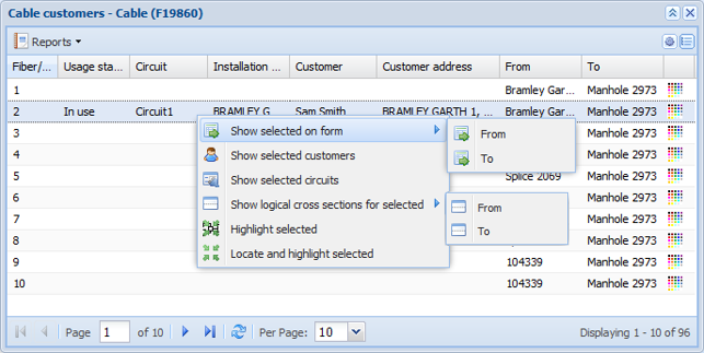
Click Customers  to open a form which includes the following information: Fiber/pair number, Circuit database ID, Circuit Identifier, Circuit Identifier 2, Contact number, Order number, Organization, Redundancy, Importance, Contract length, Comments, Circuit section database ID, Circuit section name, Usage state, installation address,Customer number, Customer, Customer address, Primary circuit, Primary section and Highlight color. You can also see the telecom premises device at the A end, the telecom premises and device at the B end and the connector in the device from the From, To and Active/Passive devices columns.
Use the right mouse button to click the row. This opens a pop-up menu, in which you can choose whether to view the form for the telecom premises at the A or B end, the customer, circuit, or the logical cross section form for the telecom premises at either end, or whether the route is highlighted and located on the map. Select Show selected circuits to open the Circuit form (for further information, see the chapter Circuit).
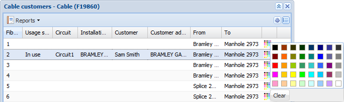
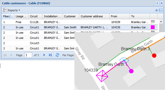
If you want to highlight a circuit on the map, select the circuit to be highlighted by clicking it on the Cable customers list with the left mouse button. You can highlight several circuits by clicking them with the left mouse button while holding down the CTRL or SHIFT key. Next, in the menu that opens when you click the right mouse button, select Highlight selected or Locate and highlight selected. You can select the colour used for highlighting each of the selected circuits on the map. To select the colour, click the colour selection box at the end of the row and select a new colour in the window that is displayed.
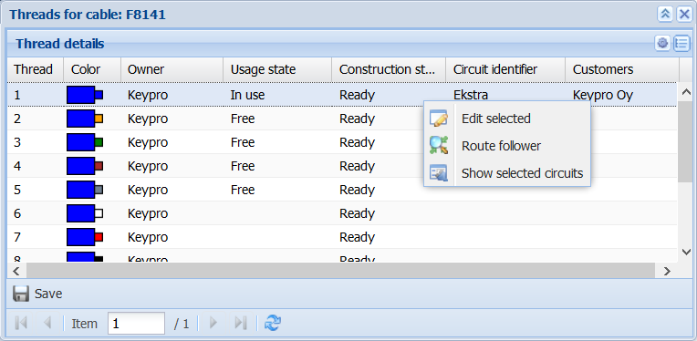
Thread details for cables
With the Thread details  function, you can add cable thread information, for example, their owners, usage state and right of use. The Threads for cable form also displays any circuit identifiers and customer information.
Double-click a thread row to edit the information in a column. Click a thread row with the right mouse button to open a dialogue box. A mass update of threads can be performed by selecting the required rows with the left mouse button while holding down the Shift key.
Edit selected  : Edit the information of the selected thread row or rows. You can update the owner, usage state, construction state, details, right of use, and the validity dates of right of use for each row.
Use the Route follower  to go to the Route follower form.
Click Show selected circuits  to go to the Circuit form where you can review the circuit for which the thread is reserved.
You can modify the column view by clicking the arrow button next to a column header. This lets you select more columns to be displayed. For example, you can add a Thread type column to be displayed. Click the Details row in a column to freely add comments related to the thread.
Do not forget to click Save to save your changes. Unsaved information is marked with  .
.
Note! The Threads for cable form includes the Circuit identifier and any customer information when physical reservations have been made on the Circuit form.
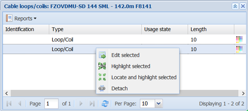
Cable loops
Use the List - Show loops function on the Cable form to view a list of the loops/coils of the cable. This list will display any loops and coils connected to the cable and their basic information. You can select the objects you want and highlight them on the map, or you can open them on an object form (click the right mouse button). Use the Highlight color
  button to select the colour you want to use for highlighting a loop.
You can remove a cable loop with the Detach function. If you remove a loop, its length will be removed from the total cable length.
Click Reports to create a List report on loops/coils (in Excel format).