Basic information on circuits
In the KeyNet tools, click Circuit
 to open the Circuitform. You can also open this form through the list of cable customers, the list of circuits on the telecom premises, the connector list for telecom premises, or the list of customer’s circuits by clicking the right mouse button and selecting it in the displayed menu. In addition, you can open the Circuit form by clicking the Open circuit button on the Logical circuit mass creation
 form.
form.
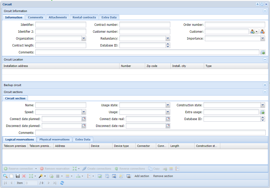
The Circuit form is divided into four tabs (Information, Comments, Attachments and Rental contracts). The content of the form consists of the following: basic data (Circuit information), installation address information (Circuit location), backup circuit information (Backup circuit), information related to circuit sections and circuit section reservations (Circuit sections). The basic data includes the common information on the circuit. A circuit can have more than one circuit section, and these sections may have different purposes and different routes. Connection reservations are made in the Logical reservations and Physical reservations sections.
On the Information tab, you can add basic data on the circuit: Identifier, Identifier 2, Contract number, Order number, Customer number, Customer, Organization, Contract length, and Installation address.
The Attachments tab is used for creating and viewing attachments.
Use the Circuit form to manage circuits, connection sections, and connections. This form can be used for creating new circuits and deleting old ones, and for editing and viewing existing circuits. You can also use the form to create a work order, to add a fault history for a circuit, and to view sub-circuits.
You can add additional comments in the Comments tab.
The Rental contracts tab is used for viewing any rental contracts related to the circuit. To add a new rental contract, go to the Rental contracts tab, which is discussed in more detail in the Rental contract chapter.
Always remember to save your changes by clicking Save  !
!
Note! Click to restore the original state of the fields for any information on the form that has not been saved.
Redundancy and importance classification
Use the fields at the top section of the form to define Redundancy and Importance for a circuit. Redundancy and Importance values can be defined on the admin user’s administration site.
In the Redundancy field, you can choose whether the circuit has partial or full redundancy or no redundancy at all. Redundant circuits have back-up components that enable the functioning of the circuit, for example, in the event that a cable is damaged.
The importance classification is determined in accordance with the instructions provided by Traficom (Finnish Transport and Communications Agency). Components that belong to a public communications network or a communication service are classified according to type, geographic scope, and number of users. The importance classification ranges from 1 to 5. The more important the service is, the higher the number.
Circuit customers
Click Pick customer to open the Customer
 form, on which you can add the customer data for the circuit. More information on the Customerform is available in the chapter Customer. Click Clear customer
 to clear the customer data for the circuit.
TIP: You can use the Circuit form’s Customer number and Customer fields as search criteria when you pick a customer. The Customerform is opened, and it displays the data for a customer picked earlier or the customers matching the search criteria in the fields. If the fields are empty, the Customerform is opened without performing a new search.
Installation address
If an installation address is not entered when a customer is added, the program will automatically select the customer’s address as the installation address. Use the Address form to add an installation address. To open the Address form, click the right mouse button to open the context menu and select Pick address. More information on the Address form is available in the chapter Address. To create a new installation address row, click the right mouse button and select Add new . To delete an installation address row, select Delete
 . To change the type of an installation address, double-click the Type field, and select the appropriate type in the menu. Click Save to save changes.

TIP: The fields in the Installation address section on the Circuit form can be used as search criteria after clearing the form. Double-click to activate the fields.
Locating and highlighting a circuit
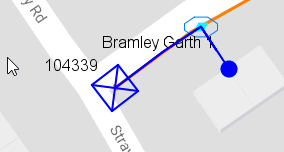
To highlight the cables connected to the connectors reserved for the circuit, click Locate and highlight at the bottom of the Circuitform, and use the functions available in the drop-down menu for the button. If several circuit sections have been defined for the circuit, the Highlight function is applied to all of them. The Highlight all function highlights all the circuits on the form.
TIP: You can use the List function to highlight the circuits on a map using different colours. The List function is introduced in the chapter List. To view the components of the Circuit section, click Show components of the section in group display
 . Group display is discussed in more detail in the chapter Group display.
You can highlight an individual circuit section by clicking the Locate and highlight button at the bottom of the circuit section. If you want to highlight a circuit section only partially, select the rows you want to highlight in the circuit section by clicking with the left mouse button while holding down the Ctrl or SHIFT key. Next, in the menu that opens when you click the right mouse button, select Highlight selected or Locate and highlight selected. Click Open in to access additional functions for selected circuit rows.
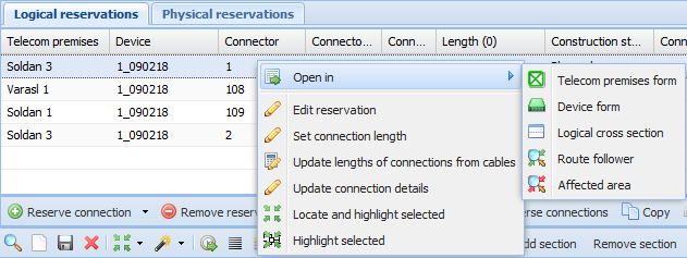
You can view the telecom premises, device, logical cross-section or affected area related to a circuit’s connector by clicking Open in. In addition, you can use the route follower function to follow the route of a circuit’s connector. You also have the option of selecting several circuit reservation lines to be viewed.
Picking circuits from the map
Click Pick from map to pick circuits from the map. The functions related to the Pick from map tool are discussed in the chapter Picking objects from the map. When you click Pick from map
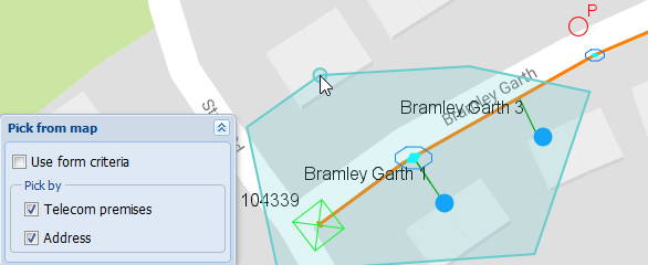
 , a dialogue box is displayed in which you can choose whether to search for circuits based on telecom premises or an installation address (both are selected as a default).
When the search is based on an installation address, the addresses in the defined area are compared with the circuit addresses in the database, and all circuits with an address matching the addresses in the defined area are displayed on the Circuit form.
When the search is based on telecom premises reserved for a circuit, the telecom premises in the defined area will be compared with the information stored in the database concerning telecom premises reserved by circuits, and all circuits with telecom premises reserved for circuit connections matching the telecom premises in the defined area will be displayed on the Circuitform.
Use the sub-menu for Pick from map to pick circuits from the map: Map view area picks the circuits in the map view, whereas Free area lets you define an area on the map from which the circuits are picked. The Existing area option is for picking an existing area, for example, circuits within a plan or service area. The Use physical reservations option is for picking circuits with physical connections to the objects defined on the map.
Connection reservations for a circuit
A circuit consists of the points of connection (connectors) of the devices located in various telecom premises and the logical connections between them. However, highlighting a circuit also requires that the physical connections between the devices’ connectors have been digitized in KeyCom.
Reserve a connection
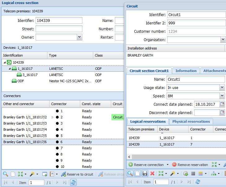
To select a connector, click Reserve connection to open the Logical cross-section form. More information on cross-section reports is provided in the chapter Cross-section. Retrieve the required telecom premises to the form. Then, on the Devices tab, select the device with the required connector. After you have selected the device, go to the Logical cross-section form, select the required connector on the Connectors list using the left mouse button, and click Reserve to circuit
 (the right mouse button can also be used for making the selection). After this, the connector in question will appear on the Logical reservations list on the Circuitform.
If one or several connection routes can be reserved for the connector that is reserved, the route options are displayed on the circuit’s Reservation of connections form.
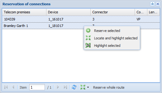
Before making the final reservation, you can highlight on the map the cables and telecom premises that are connected to connectors. To do this, click Locate and highlight on the Reservation of connections form. This button is used to highlight the cable routes related to all connectors, as was the case with the highlight function in the circuit section on the Circuitform.
You can highlight a connection route only partially. To do this, select the required rows with the left mouse button while holding down the Ctrl key and, with the right mouse button, select Highlight selected or Locate and highlight selected in the menu.
To reserve the entire connection route, click Reserve whole route. If you want to reserve only a part of the route, select the required connection rows with the left mouse button while holding down the Ctrl or SHIFT key. Next, in the menu that opens when you click the right mouse button, select Reserve selected.
Reserve a connection in telecom premises
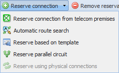
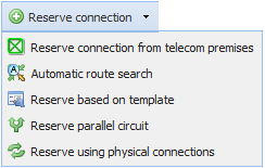
You can also choose a connector on the Telecom premises form. On the Circuitform, in the drop-down menu for Reserve connection, select Reserve connection from telecom premises. This opens the Telecom premises form.
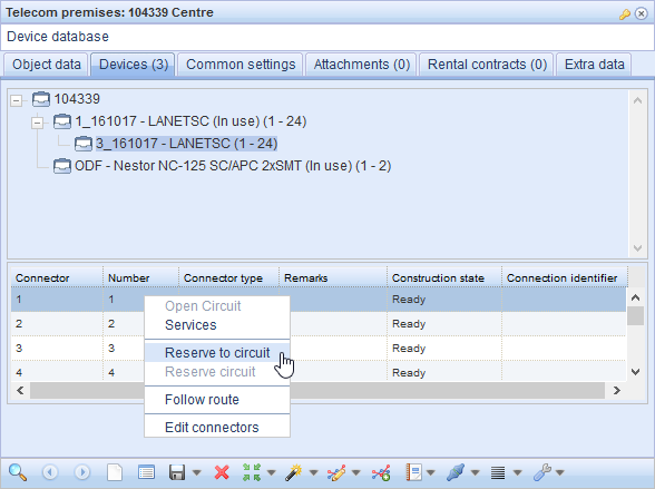
On the form, open the telecom premises where the required connector is located. Then, on the Devices tab, select the device with the required connector. After this selection, go to the connector list of the Telecom premises form and select the required connector using the right mouse button. Click Reserve to circuit.
When all the connectors of a circuit have been added to the circuit section, click Create connections . The tool creates logical KeyNet connections between the listed connectors.
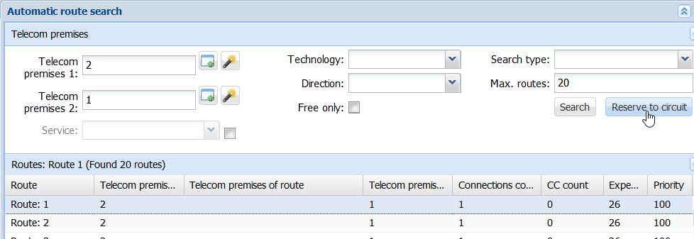
Automatic route search
Use the Automatic route search tool to automatically search for a logical route for a circuit. This function opens the Automatic route search form, on which you can search for routes between two telecom premises. Pick Telecom premises 1 and Telecom premises 2 on the form and then click Search to search for the possible routes that can be reserved for the circuit. Select the suitable route and click Reserve to circuit.
Reserve based on a template
You can use a template circuit to reserve connections for a selected circuit section on the Circuit form . In practice, Reserve based on template means that the function tries to find unreserved connections between the reserved devices of the circuit section that is used as a template. In the drop-down menu for Reserve connection
 , select Reserve based on template
 .
.

When you click Reserve based on template, a new >Circuit form is opened. The new >Circuit form is used for retrieving the circuit used as a template and for selecting the circuit section based on which connections should be reserved. At the bottom of the >Circuit form, click Reserve template to have the program reserve any free connections it finds and add them at the end of the original circuit section. The >Circuit form is closed after this. The reserved connections are displayed in the circuit section of the original Circuit form. A text Reserved Successfully is displayed at the bottom of the form to confirm that the reservation based on a template has been successfully carried out. The Information tab will display the name of the person who updated the connection and the related date.
When all the connectors of a circuit have been added to the circuit section, click Create connections . The tool creates logical KeyNet connections between the listed connectors.
Reserve parallel circuit
- In the drop-down menu for the circuit section’s Reserve connection, select Reserve parallel circuit
 .
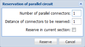
. - Enter the following information on the form that is displayed: the number of circuit sections with related connections that you want to reserve along the same circuit route and the number of threads/pairs between the reservation and the connections of the original section.
- If you want to reserve the parallel connectors in one circuit section, select the Reserve in current section checkbox. By default, all reservations are made in separate sections.
When all the connectors of a circuit have been added to the circuit section, click Create connections . The tool creates logical KeyNet connections between the listed connectors.
Reserve using physical connections
The drop-down menu for Reserve connection includes the option Reserve using physical connections if physical reservations have been made. Logical reservations are made based on physical reservations. Further information on physical reservations and circuits is available in the Making physical network reservations chapter.
Making physical network reservations
It is also possible to make physical network reservations for a circuit. You can find the Physical reservations tab next to the Logical reservations tab on the Circuit form. There are three alternative ways to make physical reservations: 1) reserving single threads, 2) making reservations based on route following and 3) automatic reservations based on logical reservations. You can find the options in the drop-down menu for Reserve connection :
:
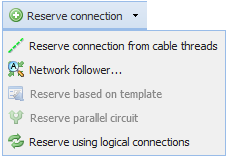
 Reserve connection from cable threads: This function opens the Cable form. In Tools
 , select Thread details. On the displayed form, click the thread row with the right mouse button and select Reserve thread to circuit. The thread you selected is now linked to the connection and visible on the Physical reservations tab.
 Network follower: This function opens the Route follower form. Click Start trace to find the route for the thread or connector you selected. The list of route objects includes the network elements related to the selected thread or connector. To select the required row or rows for the circuit, click the right mouse button and select Reserve selected to circuit or Reserve all to circuit. Further information on Route follower is provided in the chapter Route follower.
 Reserve using logical connections: This function is available if logical reservations have been made for the circuit. In this case, the physical connection will be reserved based on logical connection reservations.
Note! Reserve based on template and Reserve parallel circuit are not available for making physical network reservations.
After making the physical connection reservations, you can view your reservations on the Physical reservations tab. The columns display various kinds of information such as the identification of telecom premises, device and cable, as well as reserved threads with colour codes and construction state. The Connection state column displays a symbol illustrating the connection state.
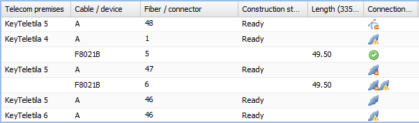
Connection state:
 OK: Connections are in order. The connector/thread on the row has no unnecessary outside connections in addition to the physical connections reserved for the circuit.
 No connection reserved: There is a connection between the connector/thread on the row in question and the subsequent row, but it has not been reserved for a circuit.
 Deviating connections: The connector/thread on the row in question has connections to external objects, which cause conflicts.
 No cable level connection: There is no cable level connection for the connector/thread on the row in question and the subsequent row (there is no cable between the telecom premises, or there is a cable between them, but its thread/connector has not been connected at the cable level to the same object as the other thread/connector).
 No thread connection/no cross-connection/no internal connection: A thread connection, cross-connection, or an internal connection is missing for the thread/connector on the row in question and the subsequent row.
Removing reservations
Both physical and logical reservations can be removed from a circuit by selecting the physical or logical connection row and clicking Remove reservation. You can also select multiple rows at once by holding down the Control or Shift key.
Reserving a provisioning port automatically
The toolbar on the Circuit form includes the Reserve provisioning port button. This function checks a circuit section’s purpose of use, the installation address of a circuit, and, based on the service availability saved in the system, the provisioning port. It also reserves the port if it finds one. Devices that belong to the provisioning port class can be defined on the admin user’s administration site. Automatic reservation of a provisioning port is made either at the beginning of a connection chain or for a new circuit section. This function notifies the user if no installation address or purpose has been selected for the circuit section.
There are three ways to search for service availability for circuits that are pre-connected, partially pre-connected or in use:
Option 1. Determine the installation addresses of a circuit sorted according to the installation addresses type. Search the database primarily for the best possible pre-connected item based on installation addresses. As a secondary option, search for the best possible partially pre-connected item. The best possible option is such that it provides a provisioning port that fulfils requirements. The second-best option does not directly provide a provisioning port, but there is one that can be used through a cross connection. The third-best option does not directly provide a provisioning port, but one can be found somewhere on the telecom premises for the pre-connected item (primarily those that are actually free). If no route fulfilling the conditions listed above can be found for the circuit, a device with similar device technology is located on the telecom premises at the circuit’s installation address, and the first available provisioning port of that device is reserved.
Option 2. The provided address is used as a criterion to search for point availability (telecom premises at the given address are searched). A device with similar device technology as the product’s technology is located on the matching telecom premises, and the first available provisioning port of that device is reserved. The line length of the product is compared to the distance between the addresses of the customer and the telecom premises. The distance between addresses is calculated using Digiroad-based road network data and by following the road network.
Option 3. The provided address is used to search for area availability to determine whether the address is within some pre-defined service area. A device with similar device technology as the product’s technology is located in the matching device or telecom premises, and the first available provisioning port of that device is reserved. The line length of the product is compared to the distance between the addresses of the customer and the telecom premises. The distance between addresses is calculated using Digiroad-based road network data and by following the road network.
Create connections
On the Circuit form, click Create connections to create or reserve the required cross-connections and internal connections. If there is a cross-connection between connectors, it is reserved for the circuit. If there is no cross-connection, this function creates a cross-connection and reserves it for the circuit. By default, only cross-connections and internal connections can be created in the system. Logical connections cannot be created.
KeyCom service availability and scheduled CSV batch runs (This function is subject to a separate order)
The system can generate service availability information as separate scheduled CSV files. The basis of service availability information is always the address and property data. This data can be produced using five different methods:
- KeyCom service availability based on connection residential addresses
- KeyCom service availability based on the address
- KeyCom service availability based on service areas
- KeyCom service availability based on telecom premises addresses
- KeyCom service availability based on potential availability
Complete the circuit
Use the Complete circuit function to mark the circuit and its connections as Completed. When you click Complete circuit, you will be asked: Are you sure you that you want to complete circuit? After confirming this, the circuit’s Usage state is In use, and its Construction state is Ready.
Additional settings for the completion of circuits
When completing a circuit, you can ensure, for example, that reservations are not removed by default from GPON and Cable TV circuit types for connectors that have been reserved for the circuit that is to be completed. Cable TV and GPON are so-called Point-to-Multipoint circuits, which typically have several circuits that reserve the same connection route all the way up to the splitter device.
When completing pre-connected VSDL-type (Point-to-Point) circuits, you can disconnect all reservations for connectors that have been reserved for other pre-connected P2P circuits. At the same time, the Usage state of these circuits is determined to be “Free” and the Construction state “Broken”. Point-to-Point circuits typically function so that each circuit uses a separate connection route from the exchange all the way to the customer.
The settings related to the purpose of use of the circuit section are defined by admin users on the admin site.
Connection direction
In the circuit section’s toolbar, click Reverse connections to reverse the order of connection reservations. This function reverses the order of reservations in the circuit section.
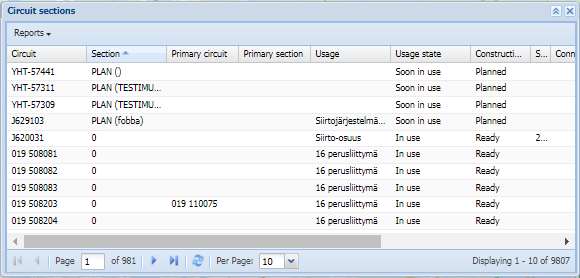
Circuit sections
A circuit may have one or several circuit sections. The basic data in the circuit section includes name, usage, usage state, construction state, speed, extra usage, and actual and planned dates for connecting and disconnecting. Each circuit section may have different purposes of use and different connection reservations. To create a new circuit section, click Add section and click Remove section to remove an existing section. Click Copy to copy a circuit section. You must click Save to accept the adding and removing of circuit sections.
Circuit section columns
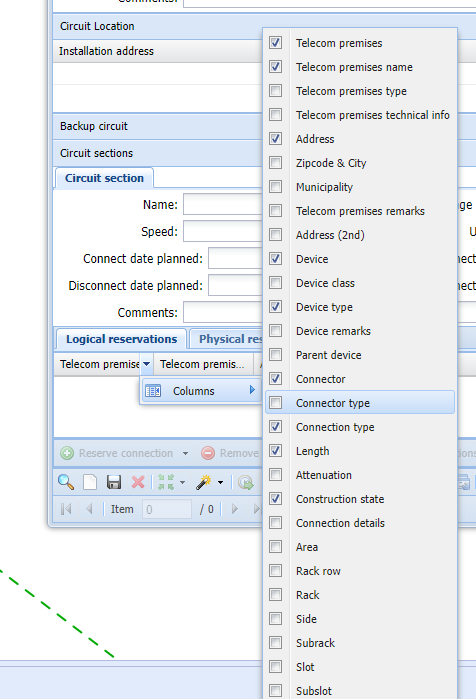
To change the order of the circuit section columns, point at a column header with your mouse, and drag it while holding down the left mouse button. You can modify the displayed columns by positioning the mouse cursor over a column header. This activates the menu. The Columns option displays a menu with functions for viewing and hiding columns. The selected columns and column widths are maintained when you browse through the circuits on the Circuitform.
Updating connection details and setting connection length
In the circuit section, position the mouse pointer over a connection and click the right mouse button to open a menu in which you can find the function Update connection details . This function opens a form on which you can update the details of the connector reserved for the circuit. The updated information appears in the Connection details column.
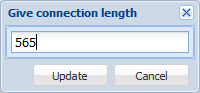
Click Set connection length to open a form on which you can manually update the required length for the selected connection. The total length of connections is displayed in parenthesis on the header of the Length column.
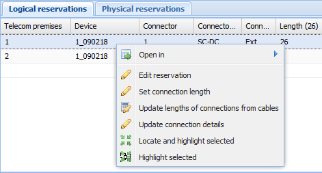
Use the Update lengths of connections from cables function to update the lengths of all the logical connections reserved for the circuit section based on the actual cable lengths. The program asks you to confirm the mass update of logical connections.
Copying a circuit section
Take the following steps to copy a circuit section and its connections:
- In the circuit section toolbar, select Copy
 .
. - Confirm the copying.
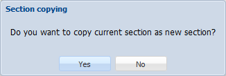
This creates a new tab in the circuit section. The tab is named. When a circuit section is copied, the name of the copy includes “_copy”.

Splitting the connections in a circuit section
- Select the connection starting from which you want to split connections to a new section.
- In the context menu, select Split to new section
 .
. - Confirm section splitting.
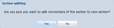
The new circuit section is named:

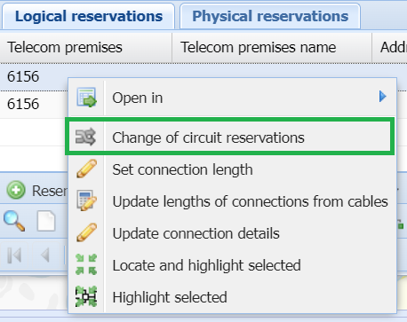
Changing the reservation of a circuit
Sometimes there might be a need to change the existing circuit reservation, for example due to a faulty circuit, to use some other free port/fiber to make the circuit function again. With the Change of circuit reservation functionality, you change the device port to some other port in the same device, or to a separate device located in the same telecom premises.
- Activate the Change of circuit reservationfunctionality from the Logical connections grid drop-down menu:
- The Cross-section
 form opens and the system automatically populates the selected device and connector information that was originally selected from the Logical reservations grid.
 - Right click the connector that you want to assign as the new replacement connector and select Accept change of reservation
 . At this point, if you want to cancel the change, click Cancel change of reservation
 .
.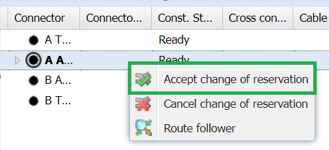
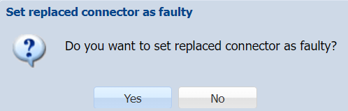
- After accepting the changes the system will allow to set the construction state of the replaced connector as faulty.
- The changes are applied into the Logical reservations grid in the Circuitform and the Cross-sectionform will close.
Viewing the components of a section in group display
View the components of a circuit section in Group display by clicking (Show components of the section in group display). Group displays are discussed in more detail in the chapter Group display.
Sub-circuits
You can view sub-circuits on the Sub-circuit form. On the Circuit, click Sub-circuits to open the sub-circuits of the selected circuit. This function opens a circuit-type form that displays basic information on the selected circuit, such as identifier, name of the circuit section, usage, speed, time slot, and comments. The parent circuit’s identifier is displayed in the header of the sub-circuit form.
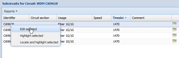
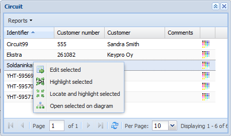
You can activate a circuit/circuits selected on the sub-circuit list and open them on the Circuit form by clicking the right mouse button and selecting Edit selected.
You can locate/highlight the selected sub-circuits on the list and define the highlighting colour as was the case with the circuit list. In the Reports menu of the sub-circuit form, you can print a list report and a report on a circuit’s sub-circuits.
Creating sub-circuits
You can reserve a sub-circuit for a circuit and define the time slot applied to the circuit route. To reserve a sub-circuit, start by creating a new circuit and click Reserve connection on the Circuitform. A Logical cross-section form is displayed, on which you can select the required telecom premises, device and connector that is used for creating a sub-circuit for the circuit to be reserved. Click Reserve circuit
 to open the Circuit reservation form. The form displays the connection chain of the circuit that is to be used as the sub-circuit, and displays the connectors reserved for the circuit in separate menus.
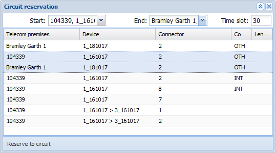
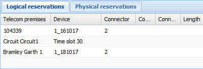
On the Reservation of circuit form, select the start and end points. The connection chain between them is reserved for the circuit. Enter the time slot applied to the sub-circuit. Click Reserve to circuit to reserve a sub-circuit for a circuit. The sub-circuit is now displayed on the connection list for the circuit section. The first and last component (start and end points) and the time slot of the circuit reserved as a sub-circuit are displayed.
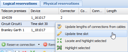
You can update the time slot reserved for a circuit. Click the right mouse button over the Time slot row and select Update time slot.
This opens the Enter time slot menu, in which you can enter the new value.
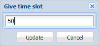
Click Update to save the time slot for the sub-circuit, or click Cancel to cancel the action.
Saving and deleting a circuit
When a circuit is saved, information on the person who updated it and the date of updating is maintained even when changes are made, for example, to circuit sections, the connections reserved for a circuit, additional usage or the attachments related to the circuit.
When a circuit is saved, the connector reservations related to other circuits are taken into account, and the states of the reserved components are taken into account in the following cases:
- Saving the construction state of a circuit section as Ready updates the construction state of the components (connectors and connections) related to the circuit section as Ready.
- When the usage state of a circuit section is saved as Free, Pre-connected, or Partially pre-connected, it is checked whether some other circuit with the status In use or Soon in use has reserved the same components. If the components reserved for the circuit have been reserved for some other circuit with the status In use or Soon in use, you will be asked the following question: Do you want to remove connections that are reserved by another circuit with state “In use” or “Soon in use?
If you answer yes, the reservations that are used by other circuits having the usage state “In use” are removed from the circuit.
- When the usage state of a circuit section is saved as In use, Soon free, or Soon in use, whether some other circuit with the status Free, Pre-connected, or Partially pre-connected has reserved the same components is checked. If the components reserved for the circuit have been reserved for some other circuit with the status Free, Pre-connected, or Partially pre-connected, you will be asked the following question: Do you want to remove overlapped connections from other circuits with state “Free”, “Unused”, or “Partially unused”?
- If you answer yes, the overlapping reservations will be removed from other circuits.
When a circuit is removed, the following is considered:
- Whether or not the usage state of all the circuit sections of the circuit is Free is checked. If not, the following notification is displayed: Circuit cannot be deleted since saved usage states of all sections are not "Free".
- The system checks that other circuits are not using the circuit. If they are, the following notification is displayed: Circuit cannot be removed since it has subcircuit(s).
Circuit diagram
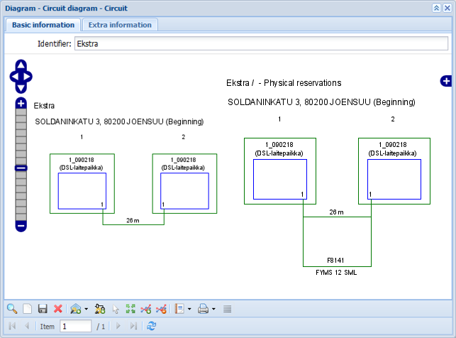
You can create a Circuit diagram of the connections reserved by the circuit. This diagram is created based on your selections.
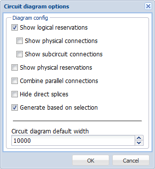
Circuit diagram settings:
- Show logical reservations: Illustrates the circuit’s logical reservations in a diagram.
- Show physical connections: Illustrates the physical network between the logical reservations.
- Show sub-circuit connections: Illustrates the sub-circuit connections of the sub-circuit that the circuit uses.
- Show physical reservations: Illustrates the circuit’s physical reservations in a diagram.
- Combine parallel connections: Combines the physical reservations of one circuit into one diagram, when the entire reservation chain is parallel (the diagram displays, for example, connectors 1–3 as numbers instead of three diagrams).
- Hide direct splices: Direct splices between cables are hidden in the diagram.
- Generate based on selection: Creates a circuit diagram based on the reservation rows you have selected.
You can also define the default width of the diagram.
After you have defined the diagram settings, click OK to view the Circuit diagram form. The diagram also includes more detailed information on the identifiers and addresses of telecom premises, as well as information on the colour coding of cables and their usage state.
View all circuits in a diagram
In the drop-down menu for Circuit diagram , click Show all circuits in diagram
 to create a circuit diagram based on multiple circuits. This function creates a diagram of all the circuits that have been retrieved to the form.
Display selected in a diagram
You can select the required circuits for the circuit diagram from search results. When several circuits have been retrieved to the Circuit form, click Show in list . In the displayed dialogue box, select the circuits that you want to include in the diagram. When a row is selected, click the right mouse button and select Open selected on diagram
 .
.
In the displayed Circuit diagram options, define your settings and click OK to create a diagram.
Reports
You can create various reports from the Circuitform, for example, circuit reports, bill of materials, and work order reports.
Circuit report
You can create separate reports on a circuit section’s logical and physical connections.
Click Reports to open the Circuit section’s connections dialogue box. Select either Logical reservations or physical reservations as the report type. Based on the reservation type, a circuit report will be created with logical or physical reservations and their start and end points.
Bill of materials
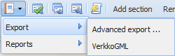
Use the Bill of Materials function in the Reports menu to create a bill of materials for the circuit’s connections. The bill of materials lists all network elements that the circuit is using. You can save the report as a file or open it directly in Excel. The components included in the bill of materials can also be saved in Finnish VerkkoGML format by using the Export function. Exporting to Finnish VerkkoGML is described in more detail in the chapter Exporting to VerkkoGML.
A work order report
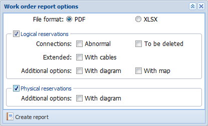
You can print a Work order for the circuit through the Reports menu. A work order report is a report on the circuit’s logical and physical reservations in either Excel or PDF format. On the Work order report options form, you can define the logical and physical reservation information that you want to include in the extended work order:
- Abnormal reservations and reservations to be deleted
- Cable information
- Additional diagram information and map extract If you select the With map checkbox, the printout will include an additional page with the circuit highlighted on the map.
- Physical reservations diagram
Error history for a circuit
You can activate the circuit error history function in the toolbar of the Circuit form. Click Circuit error report to open a new form for entering the error history of the circuit.
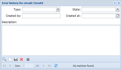
On this form, you can enter information on the error type, state, creator, and creation date as well as provide more details as free-form text. These fields can also be used as the search criteria for the form. In addition, the header of the form displays the identifier of the circuit that the error is related to. Click Show in list to open the Circuit error history list for the circuit in question.
The Circuit error history form is by default pre-populated with the error history details related to the circuit and organised by creation date, error type, and state. You can search the form based on this information. For example, you can retrieve all errors of the circuit based on type. Click Clear to clear all information on the Circuit error history form. Click Save
 to create a new error history row and to update existing information. Click Delete
 to delete the selected error history detail.
Viewing the components of a circuit in group display
View the components of a circuit in Group display by clicking Show components of the circuit in group display  . Group display is discussed in more detail in the chapter Group display.
Circuit backup
You can set Backup circuits for the Primary circuits in KeyCom environment. In the middle of the Circuit form, there is the Backup circuit column. The info of the backup circuit will appear there.
Start by right-clicking an empty section and then click Link backup circuit . This will open a new >Circuit
 form, in which you can add the necessary info. Choose Use as a backup circuit
 in the toolbox. It is located at the bottom right corner of the >Circuitform. This will assign the selected backup circuit to the primary circuit in question.
You will find the following columns in the Backup circuit section:
- Primary circuit
- Primary circuit section
- Backup circuit
- Backup circuit section
- Backup ruleset (A list showing the rules that can be set for each environment). Note! Double-click the section to open the dropdown menu to choose a rule.

Functions of the context menu
You can find all functions of this feature in the context menu Open it by right-clicking the column after you have added a Backup circuit.
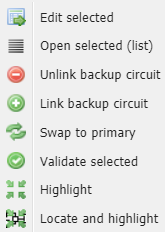
 Edit selected: Open a circuit on a backup circuit form and edit it.
 Open selected (list): Open the primary circuit and the selected backup circuits (with circuit sections) into a separate circuit section list.
 Unlink backup circuit: Unlink a backup circuit from a primary circuit.
 Link backup circuit: It links a backup circuit to a primary circuit. If the selected circuit is already linked to a primary circuit, this action is not available.
 Swap to primary: Swap the selected backup circuit a primary circuit and make any changes related to the existing relationships between other primary and backup circuits.
  Validate selected: Validate the rules for the selected backup circuits in relation to the primary circuit.
 Highlight: Highlight the selected circuits on the map in the default highlight color (blue) based on the components assigned to the circuits.
 Locate and highlight: Locate the selected circuits on the map and highlight them in the default highlight color (blue).
Circuit section list
Open the Circuit section list by clicking the Open selected (list) from the Context menu or in the submenu of the Circuitform. The list shows both the primary circuit and the backup circuit with the selected circuit sections. The Circuit section list will be automatically populated based on the search set of the Circuit
 form with all basic information of the circuit section.
The Circuit section list can be also used in cases when you need more details of circuit sections, such as name, usage, usage state, construction state, or speed.
If the link between primary/backup circuit was not originally made at the circuit section level, the Circuit section list will show both the primary and the backup circuit with all circuit sections and their basic information.
Grouplist display list options
When you choose to show all the components on Group display list you can also decide whether you want to show common components only or not. First, select multiple circuit sections in the Circuit section list to open the Grouplist options window. To select multiple rows, hold down Shift on the keyboard while selecting the rows. Then right-click and click Show components of the circuit in group display.
Show only common components: Lists all telecom premises and cables that can be found in the logical and physical reservations for all selected circuits/circuit sections.
Backup circuit ruleset: Activates a selection list where the user can select environment-specific configured backup rules. Read more about the Backup circuit rulesets.

Backup circuit rules
It is possible to set up environment-specific Backup rules for validation in the Circuit backup rule manager. The Backup circuit ruleset function opens a list where you can choose rules for the Backup circuits. You can access these rules in two different ways:
Option 1: Double-click the field under the Backup ruleset section on a Circuitform to open a drop-down menu.
Option 2: Open Grouplist options.
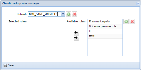
Managing circuit backup rules
To manage the circuit backup rules, click the Manage circuit backup rules tool on the toolbar of the Circuit
 form. Using this tool, you can create or choose preconfigured rulesets for the backup circuits.
To create a new circuit backup rule, click Add new in the Available rules field. It will open a Create circuit backup rule form. Specify a label for the rule and choose the rule type.
You can also create a new rule type by clicking Add new on the Create circuit backup rule form. When creating a new rule type, you must at least fulfil the Rule function and Txt fields. Click Save
 to save your work and return to the Create circuit backup rule form where you can now select the rule in the dropdown menu. When you click Save
 , the new Backup rules can be found in the Available rules section.
To activate a Ruleset on the Circuit form, clickAdd new
 or choose a pre-existing Ruleset in the drop-down menu. To move rules from the Available rules field to the Selected rules field, right-click the rule(s) that you want to add. Then click the arrows in the middle of the form, depending on which direction you want to move the rule between the fields.
Read more about activating Backup circuit rulesets on the Circuit form in Backup circuit rules.