Information on the Conduit form
In addition to the basic functions that were discussed in the chapter Buttons on object forms, the Conduit form is used to manage cables and ducts connected to conduits and any cables that are connected to them.
ALWAYS remember to SAVE your changes by clicking the Save button . For example, if you add ducts to a conduit, you must click save while doing this in order to be able to add a cable to the duct.
TIP: You can search conduits for the form by using duct attributes as search criteria.
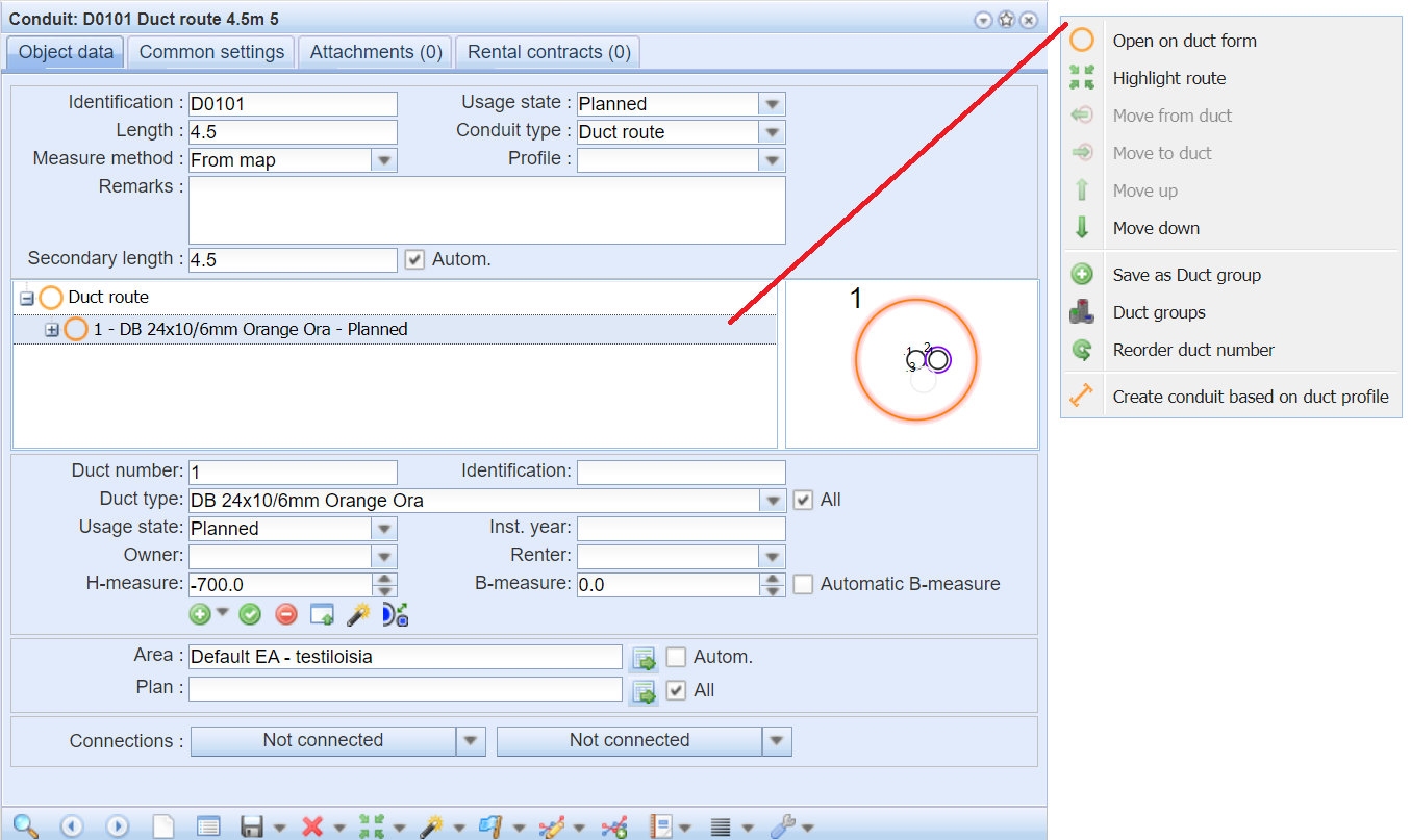
In the example figure below, you can view both a list and a cross section of the ducts and cables connected to the conduit. Manage the ducts and cables of a conduit with the functions available in the context menu that is displayed when you click the right mouse button.
Functions of the context menu
You can manage the ducts on the Conduit form by opening the context menu. You can open the menu by right clicking the duct column.
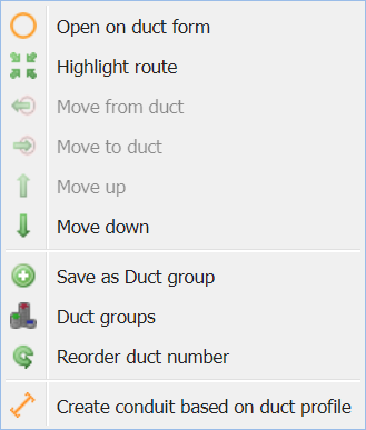
 Open on duct form: This function allows to open the selected duct on the Duct
 form.
form. Highlight route: This function locates and highlights the selected duct on the map with the blue highlight color.
 Move from duct: This function moves the selected duct out of the parent duct and displays it in the list at the level same level.
 Move to duct: This function moves the duct inside the previous duct on the list. The desired parent duct must be on the same level in the hierarchy before moving a new duct into it. The duct location on the cross-section image moves inside that duct.
 Move up: This function moves the position of the duct up by one step.
 Move down: This function moves the position of the duct down by one step.
 Save as Duct group: This function saves the Duct group.
 Duct groups: This function opens the Duct group form.
 Reorder duct numbers: This function updates the number of the selected duct in the form to the new number selected by the user and rearranges the ducts in the list based on the new numeric order.
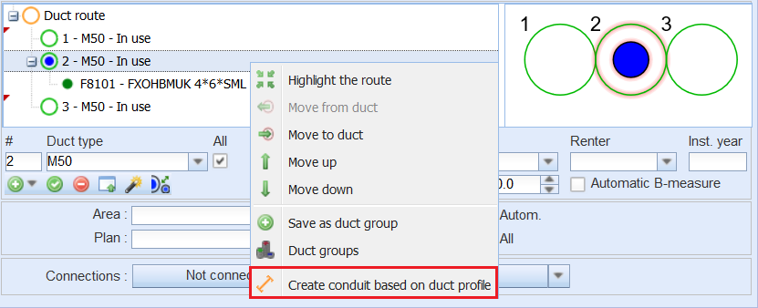
 Create conduit based on duct profile: This function splits the chosen conduit or duct selected from the form based on duct profile. Read more Creating a conduit based on a duct profile.
Secondary length (this function is subject to a separate order)
Secondary length indicates the eligible length of the conduit. The Secondary length is calculated from the total length of the conduit, minus the parts of the conduit that run within the Unsubsidised areas. More about Unsubsidised areas in the paragraph Adding a point buffer.
Next to the Secondary length field is the Autom. check box, which when checked, the program calculates the Secondary length with each save, if the geometry has been changed. If you do not select the Autom. check box, you can define the Secondary length yourself or leave the field empty.
You can view the Secondary lengths of the conduit with the Reports tool of the Plan
 form, if the conduits are connected to a plan. More about the report in Plan report.
The properties of ducts and cables in a conduit
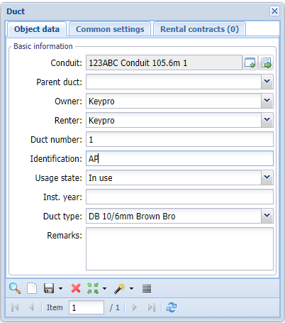
In addition to the information on the properties of a conduit, the Conduitform lists the ducts and cables that the conduit includes. For ducts, the information includes the duct number (displayed in the cross-section figure in the top left corner of the duct), duct identification, duct type, usage state, owner, renter, and installation year. For cables, the property information includes the type, ID, state, owner, and installation year.
The information on ducts (the circle symbol) and cables (green dot symbol) in a conduit can be viewed on the form.
The B and H measures of ducts and cables in a conduit
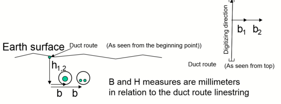
The information related to a duct can be edited in active state. The information on B and H measures is provided in millimetres in relation to the conduit’s location on the map. The B measure indicates the horizontal location of a duct in relation to the conduit location. The H measure indicates the depth of the duct in relation to the conduit location. This can be a negative figure if the conduit has been measured at ground level, and it can be positive if the conduit has been measured at the bottom of the ditch. The B and H measures can be indicated to one decimal place.

A cross-section of the conduit’s ducts and cables
The location of ducts and cables in a conduit is illustrated with a separate cross-section illustration. Ducts are illustrated as hollow circles, with the duct number displayed in the upper-left corner. The colour of a duct depends on the colour defined for the duct type in question. If no colour has been defined for the duct type, the duct is marked in grey.
Fo example, the duct selected on the list is highlighted in the cross-section in the figure below. The cross-section illustrates ducts with type-specific colours. In this illustration, the empty sub-duct “.1” has been selected, and it has been placed in the orange duct “1” with the sub-duct “.2”. A cable has been installed in the sub-duct “.2”. If a duct contains several cables, the number of cables is displayed in the middle of the cable symbol. For example, duct “2” contains two cables. A cable can be installed directly in a conduit, in which case the cable number is displayed in the cable’s top left corner. Cable “1” has been installed directly in a conduit.
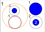
Cables are illustrated as blue circles and if a duct contains several cables, the number in the middle of the cable symbol indicates the number of cables in the duct. If a cable is installed directly in a conduit, and not in a duct, the cable’s sequence number, which is automatically assigned and cannot be edited, is displayed in the top left corner of the cable. The location and size of ducts and cables is illustrated in proportion to each other, meaning that a duct of the same size may be illustrated in various sizes in different cross-sections depending on the conduit’s size and the number of ducts and cables in the cross-section illustration. The size of the blue cable symbol is not equivalent to the actual shape or diameter of a cable.
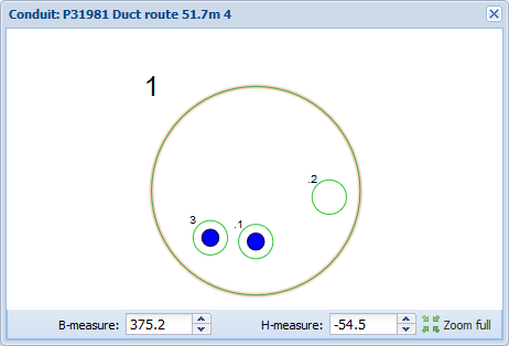
The ducts and cables in a conduit can also be opened in a new window by clicking Open conduit profile in a new window on the Conduitform. On this form, you can modify the location of the highlighted ducts and sub-ducts by dragging them to a new location or by changing the B and H measures.
In the example figure below, a conduit profile opened in a new window. The conduit contains one duct, which has three sub-ducts, with cables installed in the sub-ducts .1 and .3.
Viewing a cable installed in a conduit or duct
- Select the cable you want to view.
- In the context menu, which you can open by clicking the right mouse button, select:
- Open cable to view the Cable form displaying the information on the cable in question.
- Zoom to cable to center the map on the selected cable.
Conduit reports
Click Reports under the Export tool on the Conduitform to create reports. You can create Excel reports on intersected properties linked to a conduit and reports on all intersected properties or you can create a bill of materials on the conduit elements.
Click List to open the Conduit dialogue box, which displays information on all the conduits that were retrieved to the form. You can edit the information in the columns. The options under Reports
 enable the creation of reports on rental contracts, bills of materials and lists. Click the List tool and select the appropriate option to create a group display and reports on intersected properties.
Modifying conduits
Connecting a conduit, modifying, moving, and disconnecting a geometry, and measuring length are discussed in the following chapters.
Connecting a conduit
A conduit’s connections are displayed at the bottom of the Conduit form. A conduit can be connected to a manhole at both ends or only at one end. If a conduit is connected, the menu displays the information on the connected objects, such as Manhole 1082. If a conduit is not connected, the text on the menu is Not connected. You can access the connections in the drop-down menus.
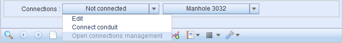
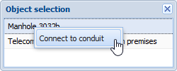
To connect a conduit, select Connect conduit. The software automatically searches for point objects within five metres of the start or end of the conduit and opens the objects in the Object selection window. In addition, you can select the network element to be connected by defining an area on the map. If the defined area includes more than one object, an Object selection window will be displayed. Click a network element with the left mouse button to highlight the object on the map. This makes it easier to select the correct object. To create a connection, double-click or click the object with the right mouse button and then select Connect to conduit. When the connection has been successfully made, the following text will be displayed on the form: Conduit connected successfully, and the name of the connected object appears in the Connections field.
Click Disconnect conduit to disconnect a connection. When this has been successfully carried out, you can see the following text at the bottom of the form: Conduit disconnected successfully. Select Edit to open the form for the object in question. You can then view its information or locate it on the map.
Moving a conduit
Moving a conduit is carried out in the same way as moving other line objects. This function is discussed in more detail in the chapter Moving a line object to a line.
Splitting a conduit
Conduit splitting is carried out in the same way as splitting other line objects.
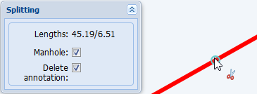
To add a manhole to the location where you split a conduit, select the Manhole checkbox in the dialogue box for Splitting. The cables in the conduit remain unchanged after the splitting.
Modifying the geometry of a conduit
Modifying the geometry of line objects, such as conduits and cables, is discussed in the chapter Modifying the geometry of a line object.
Measuring the length of a conduit
You can use the Measure length tool in the Modify menu to measure the length of a conduit on the map. This function enables the distance to both ends of the conduits to be reviewed. For example, in the example figure below, the length from the start of the conduit/length to the end of the conduit.
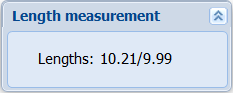
You can add a Conduit annotation with the Length measurement tool if you click the conduit with the left mouse button. Annotation creation is discussed in more detail in the chapter Annotations.
Creating a conduit based on a duct profile
Use the Conduitform to create a new conduit based on an existing duct profile.
- From the list of ducts, select the first duct of a series from which you want to copy ducts to a new conduit.
- Click a duct with the right mouse button and select Create conduit based on duct profile.
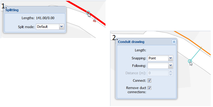
- Select the drawing settings for the required conduit and split the conduit as necessary. Select Remove duct connections to remove any existing cross connections for ducts if there are no cables in the duct. The Split conduit option lets you select the point of splitting the conduit if the starting point of the new conduit is in the middle of the original conduit. After the split has been performed, select the conduit for which the automatic duct cross connections should be created. A profile change is added to the point of splitting.
In the example figure below, dialogue boxes for Conduit drawing based on duct profile: 1. Split the chosen conduit 2. Digitize a new conduit using Conduit drawing settings.
- Digitize a new conduit on the map. You can create a new conduit from the manhole or telecom premises to which the selected original conduit is connected. If both ends of the original conduit are connected to a manhole or telecom premises, the user can separately select the end to which the new conduit is created and connected.
- The function has automatically created a new conduit, the conduit profile of which displays the duct hierarchy from the selected row on the duct list to the end of the duct rows. Based on this hierarchy, duct cross connections are automatically created with the selected duct and its sub-ducts.
Connecting a cable to a conduit or duct
When you have created a conduit, you can connect a cable to the conduit or its duct. Select the conduit or duct on the list that you want to use for connecting a cable.
Pick a cable:
either a)
- Click Pick cable from map
 .
. - Define the area where the cable is located.
- If there are several cables in the area, select the correct cable from the list.
or b)
- Open the Cable form.
- Check if the form includes the required cable. If necessary, retrieve the cable to the form.
- On the Conduitform, click Pick cable from cable form
 .
.
Adding and modifying ducts on Conduit form
Ducts and sub-ducts can be added to conduits, and the related information can be modified. The following sections introduce different ways to add and modify ducts.
Adding a duct to a conduit
- Enter the duct information. Duct type and Usage state are mandatory fields.
- Select the Automatic B-measure checkbox if you want to add more than one duct and want the B measure automatically calculated based on the diameters of the added ducts.
- Click Add new duct
 to add the duct to the list. The duct then appears in the figure and at the selected level of the list.
 - Click Add new duct
 as many times as you need to create new ducts. Edit the duct information if you want to add ducts of different type. If the Automatic B-measure checkbox is selected, the B measure of a new duct is automatically calculated based on the duct’s diameter.
 - When you are ready, click Save form
 to save changes.
Mass insertion of microducts
It is possible to add a new duct type or an existing duct profile at once to the entire conduit/duct route. The function is available on the Conduit  form.
form.
Activating the functionality:
- Open the Conduit
 form.
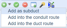
form. - Open the drop-down menu next to the Add new duct
 button. With the Add into conduit route and Add into the duct route functions that open from the drop-down menu, you can choose whether a new duct is added to a topologically connected conduit route or to a duct route formed by duct cross-connections.
Note! The new duct type/profile is always automatically placed at the end of the existing conduit-specific duct numbering order.
Adding a duct type into a conduit route:
- Adding the duct type to the conduit route is done with the Add into to the conduit route.
- Choose the desired channels from the map. They will open on a separate conduit list form. The connection status shown in the list will indicate if some selected conduits are not topologically connected to telecom premises or manhole. It is also possible to completely reorder the conduits in the list, if all the selected conduits are not topologically connected to each other or the conduits were selected from the map in the wrong order. You can delete channels with the Delete
 function.
 - Click the Create ducts button to create ducts for the conduits you selected.
Adding a duct type into a duct route:
- First, open the Duct connection dialog by selecting a conduit from the map.
- The Duct connection dialog form has the option to choose whether the selected duct type is placed next to or inside an existing duct route (the system also allows selection of a partial duct route).
- With the Inside function, a new duct or duct group can be added in the middle of every duct on the route. If that choice is not made, the B and H dimensions can be used to give values for new pipes. The new pipes are placed based on the dimensions given in the profile.
Click the Create button to create the ducts.
Updating the property values for ducts
- In the list or the cross-section illustration, select the duct you want to update.
- Edit the fields as necessary.
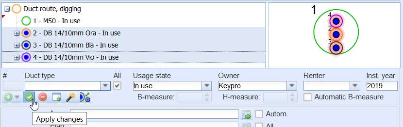
- Apply the changes to the conduit structure by clicking Apply changes
 .
. - Click Save
 to save changes.
TIP: To change the usage state of all the ducts in a conduit to In use, select In use as the usage state of the duct and click Save form. The software will ask the user to confirm the usage state change.
Adding a sub-duct to a duct
- Select the duct you want to use for adding a sub-duct.
- Define the information on the duct that is added. When adding a sub-duct, the fields for B and H measures are not relevant, because they are defined based on the outer duct in which the sub-duct is automatically installed.
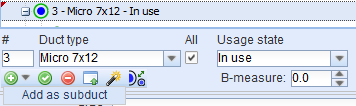
- In the drop-down menu for Add new duct
 , click Add as sub-duct to create a sub-duct.
Removing a sub-duct from a duct
- Select the sub-duct you want to remove from another duct.
- In the context menu, select Move from duct
 to move the sub-duct from the duct. It is then displayed on the list at the same level as the outer duct, but in the cross-section illustration it remains within the outer duct.
 - If necessary, change the duct location by editing the B and H measures.
Removing ducts from a conduit
- Select the duct you want to remove.
- Click Remove duct or cable
 .
. - Click Save
 to save the changes.
Note! If a cable is also connected to a duct, the cable will also be removed from the conduit.
Transforming a duct into a sub-duct in another duct
- Select the duct you want to transform into a sub-duct.
- On the list, the duct you want to transform into a sub-duct must be below the duct you want to use as the outer duct. To move the duct to the correct place, click the right mouse button and, in the context menu, select Move up or Move down.
- In the context menu, select Move to duct
 to make the duct on the list a sub-duct of the previous duct at the same level. In the cross-section illustration, the duct that is made a sub-duct is then placed inside the duct that was above it on the list.
Note! The physical size of the duct that you want to change into a sub-duct must be such that it fits inside the outer duct.
Mass modification of ducts
From the list of ducts, you can select more than one duct to be modified. To do this, click the Ctrl key while you select the duct rows.
- You can modify the properties of more than one duct, excluding the duct number and the B and H measures. To do this, select the data you want to update and click Apply changes
 .
.
Or:
- You can move several ducts simultaneously in a duct group by right-clicking and selecting one of the available Move options.
Or:
- To remove several ducts at once, click Remove duct or cable
 .
.
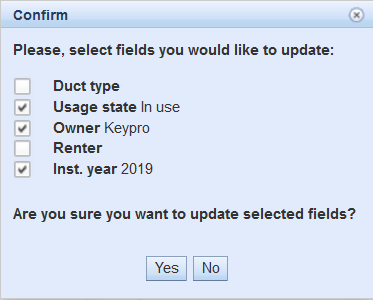
You will be asked for a separate confirmation when you carry out mass deletions and updates.
Duct form
The Duct form can be used to create and edit ducts and sub-ducts, in addition to the basic functionalities that were introduced in the chapter four, Buttons on object forms. The information in the Duct
 form can also be edited in the Conduit
 form.
form.
Adding ducts on Duct form
Ducts and sub-ducts can be added to conduits, and their information is editable. The following paragraphs introduce different ways of adding and editing ducts.
- Fill in the mandatory information. Mandatory fields are Type and Usage state.
- Choose a conduit for the duct by clicking the Pick conduit from form
 button from the Conduit field.
 - Create or select an existing conduit and click the Update to form
 button in the right corner of the Conduit
 form toolbar. The ID and Length of the conduit can now be found in the Conduit field of the Duct
 form, which means that the conduit has been connected successfully.
 - Save the changes with Save
 .
.
Note! You can place a duct into the parent duct from the Duct form. Select the Parent duct field from the Objects data and open the options from its drop-down menu.
Updating duct information on Duct form
- Select the duct that needs to be updated.
- Make the wanted changes on the fields.
- Save by clicking Save
 .
.
Duct groups
You can create and add various duct groups to conduits. Adding and modifying duct groups is discussed in the following sections.
Adding a duct group in a conduit or duct
You can add a duct group by selecting a) a group as the duct type (marked with *** on the drop-down list for Duct type) or b) by importing a group from the Duct groups form.
- When you use the Duct type selection:
- Select a type marked with *** as the duct type.
- Click Add new duct
 to add a new duct group in the illustration and at the selected level on the list.
 - Click Save form
 to save changes.
 - When you use the Duct group
 form:
form: - On the duct list, position your mouse pointer over the conduit and select Duct groups.
- Select a duct group for the form based on its name and/or attached comment.
- On the Conduitform, select the duct next to which you want to create a duct group.
- Click Create ducts to conduit
 to add the new duct group in the illustration and at the selected level on the list.
 - Click Save
 to save the changes.
Creating a duct group
- Create ducts to conduit without saving the data, as instructed for Adding a duct to a conduit.
- Save the new duct group using the right mouse button to select Save as duct group while your mouse pointer is over a duct.
- You can also retrieve an existing conduit to a form and save it as a duct group for the duct structure.
Creating a duct group based on duct profiles
You can create duct groups based on duct groups created on the Conduitform.
- On the list, select the duct or conduit row that you want to use to create the new duct group. The new duct group is formed in accordance with the duct profiles that belong to the selected row.
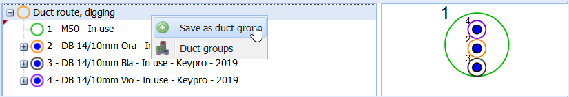
- Right-click and select Save as duct group
 .
.
Name the duct group in the Duct group dialogue box that is displayed.
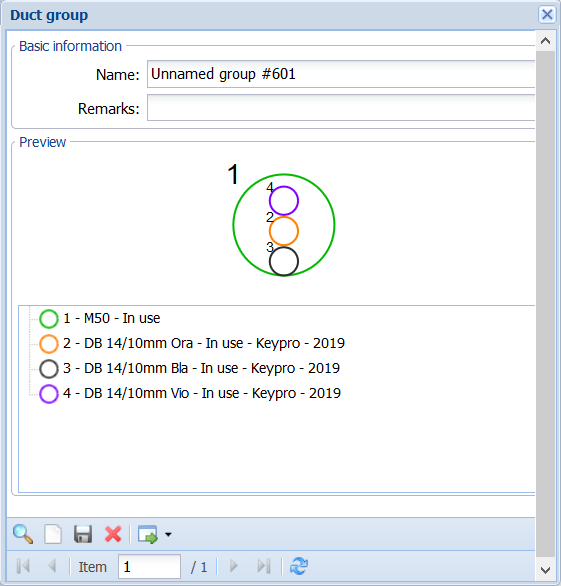
You can either click Saveto save the duct group or click Create ducts to conduit to create the duct group in question in the open Conduitform. You can add the duct group you created as a sub-duct to the Conduit form by using the Create ducts to conduit sub-selection.
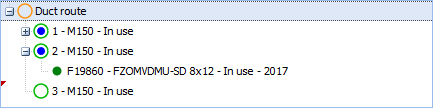
In the figure below, the duct group that was added is included in the list and marked with the number 2 in the figure.
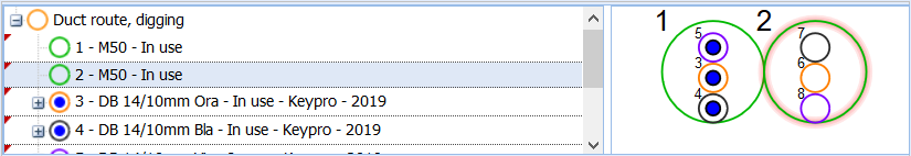
Save the Conduitform.
Modifying a duct group
You cannot actually modify a duct group, but you can use a duct group to create a new, modified duct group on the Conduit form.
- Add the duct group you want to modify to an empty Conduitform, according to instructions provided in the chapter Adding a duct group in a conduit or duct.
- Make the required changes.
- Save the new duct group using the right mouse button to select Save as duct group.