Ducts are line objects. The two object forms for ducts can be found in the drop-down menu for Duct tools  . Click Sewer duct
  to open a form that is used for sewer, rainwater and mixed water ducts in sewer and pressure sewer networks. Click Water duct
  to open a form for ducts belonging to water networks. The use of buttons common to both forms is discussed in the chapter GENERAL FUNCTIONS OF THE OBJECT FORMS.
Property and location information
To start creating a new duct, complete the form. Mandatory fields are marked with an asterisk (*) on the form. After filling in the data, click Create  to create an object on the map. The length (2D length and 3D length) of the object you created will then be displayed on the form, and the location and property information will be stored in a database. When you click the Create button, the Drawing options dialogue box is displayed. The related functions are described in the chapter Snapping and following (settings for drawing and modifying).
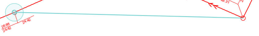
A new duct can be connected to a node as soon as it is created. When digitizing a duct, use the Snapping function: hold down the Shift key while clicking the left mouse button over the node. The duct will then be connected to the node and the following text is displayed at the bottom of the screen: Snapping completed. Snapped to object X. If the text Snapping failed is displayed at the bottom of the screen, you have tried to connect the duct to an object that it cannot be connected to. When the Snapping function is active, the mouse pointer on the map changes to a light-blue circle. Finally, end the digitization by first clicking the left mouse button at the end point of the duct and then the right mouse button. Click Save. The elevation values for the nodes will be displayed on the form in the start and end node fields, and the location and property information will be stored in a database. The elevation used for the connection is discussed in more detail in the chapter Drawing options and duct elevation.
In the example figure below, a new duct can be created between two nodes by snapping to the nodes, that is, by connecting the duct to them.
Similar property information is entered on the Sewer duct and Water duct forms, but the Sewer duct form is used for sewer ducts and rainwater and mixed water ducts. The Water duct form is used only for water network ducts. For example, water ducts are displayed on the map in blue, sewer ducts in brown, and rainwater ducts in green. Before or after creating a geometry, enter the other property information on the form.
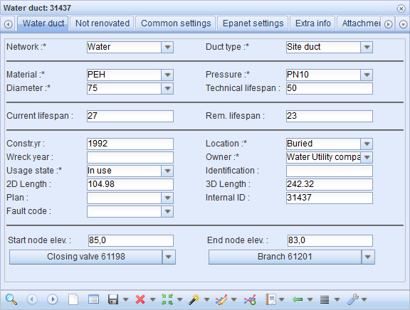
Information on the technical lifespan can be stored in the system for each duct type (Material/Diameter). The software will automatically calculate the current and remaining lifespans for the duct based on the technical lifespan and installation year. Users cannot themselves enter the values in these fields, but the values can be used, for example, in various searches.
Other property information is selected from the menus or entered into fields. Click Save form  to save the information. The program will automatically calculate the object's length on the form on the basis of the object’s location information. You cannot change the values in the Length field manually.
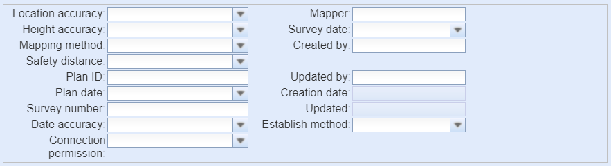
The Common settings tab is used for entering information on location and height accuracy, mapping, planning, and the saving of data. The Common settings tab is similar for both duct and node forms. On the Extra info tab, you can save free-form text.
Start and end node information
Information on the start and end nodes and their elevation and tools for disconnecting and connecting nodes can be found at the bottom of duct forms. If a node is disconnected, the same button can be used to connect a new node to the duct. With the Snapping function, ducts can be connected to nodes already when the ducts are being digitized, or this information can be updated later. The ID for start and end nodes is the ID of the node at which the heads of the duct end. To view the details of the node, open the drop-down menu of the node and click Edit node to open the node’s form.

The node’s elevation is displayed in the Start node/elev. and End node/elev. fields. You can highlight the start node on the map by clicking the start node’s ID button. Similarly, you can highlight the end node on the map by clicking the ID button of the end node. The nodes are highlighted as red squares on the map.
To disconnect a node from a duct, open the node's menu and select Disconnect. To connect a duct to a node, go to the drop-down menu, select Connect, and hold down the left mouse button to define on the map the node that you want to connect to the duct. If the node in the defined area is too far away, a notification saying that the connection failed will be displayed.
If you pick more than one node on the map, an object selection list with all the nodes in the defined area will be displayed. To select the correct node from the list, double-click it or click the right mouse button over the correct node and click Select target.
Duct renovation
The renovation information on a duct is saved on the Renovated/Not renovated tab. If the duct has been renovated, the tab’s name is Renovated. Similarly, if the duct has not been renovated, the tab’s name is Not renovated. Renovation can take place either for the entire duct between two nodes, for a defined length, or for some other section of the duct. If renovations have been saved for the duct, they are listed on the tab. The renovation information includes the mandatory fields Swage lining category and Method, and the non-mandatory fields Lining part, Lining year, Length, Material, Brand, Thickness, and Diameter. Renovations are stored in the system by clicking Add new renovation  .
.
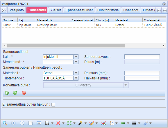
A unique ID is automatically saved for a renovation. Scroll the bar to the right to view all information. The geometry of the lining will be automatically saved in the system.
A renovation can be modified by activating its details. On the list, click the renovation line in question with the left mouse button. Click Apply changes  to update the information. Renovations can be removed by clicking Delete renovation
  when the renovation line is active. This will prompt you for a confirmation: Are you sure you want to delete duct renovation? Select Yes to delete the renovation or No to cancel the deletion. The text Deleted successfully will be displayed at the bottom of the form and the renovation will no longer be listed.
Duct renovation by digging
If the renovated duct is no longer used and has been replaced with a new duct, information on the replaced duct can be added to the new duct on the Renovated tab. In this case, a new renovation with the following Swage lining category and Method will be added to the duct: By digging.
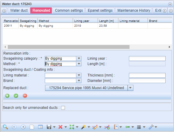
Once the renovation has been saved, go to the drop-down menu for Replaced duct to select the duct that the new duct replaces. To define the duct on the map, hold down the left mouse button and draw a rectangle that includes the required duct. When a duct has been selected, you will be asked whether the geometry of the replaced duct should be deleted.
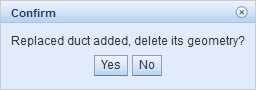
Click Yes to delete the geometry of the replaced duct. The geometry of the replaced duct has been now deleted and the Locate and Modify tools are not available but its information is retained in the system, for example, for reporting purposes. The connections to the existing network have been deleted separately. Click No to maintain the duct geometry.
Note! Remove the connections between the deleted duct and the existing network.
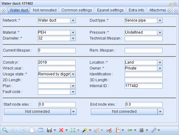
To access the form of the replaced duct, select Edit in the drop-down menu for Replaced duct. The usage state of the replaced duct has been changed to Removed by digging.
Duct condition classification
Condition info tab on KeyAqua Water duct  and Sewer duct
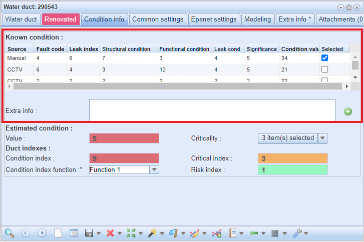
  forms show the various known condition information (structural condition, functional condition, leaks etc.) for the active duct on the form. It also shows the duct’s estimated condition information, which includes the criticality value and estimated condition based on the build year and material. By using the known condition values with the estimated condition values certain condition indexes are calculated as the result.
Known condition of the duct
The known condition information is gathered from different sources, for example, REST API and CCTV-imaging. The information is shown in the grid at the upper part of the form.
The meaning of the fields:
- Source: Tells where the information came from. For example, from CCTV.
- Fault code: A condition factor from a 3rd party.
- Leak index: A condition factor from a 3rd party.
- Structural condition: The value that is given for the physical condition of the duct.
- Functional condition: The value that is given for the functional condition of the duct.
- Leak condition: The value given for the condition based on leaks in the duct.
- Significance: The value given for the significance of the leakage.
- Condition value: In CCTV, this is the value calculated based on the structural, functional and leak condition values.
- Selected: In case of a duct having many rows of information, the selected one is used in the index calculation.
The fields with bolded headers are the ones that are used in the Condition index calculation. These fields are Source, Fault code, Leak index and Condition value. There is also an Extra info field below the grid for adding free-form text about the condition of the duct. To add a new field for the Known condition grid, click the Add new detail row button.
Estimated condition of the duct
Estimated condition section can be found below the Known condition section. It consists of two fields: Value and Criticality. The Value is fetched from API provided by duct condition service. Read more in Duct condition information. It uses the build year and the material as parameters and returns an integer value.
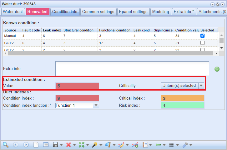
There are four different types of criticalities. Multiple choices can be selected. Criticality tells whom the condition of the duct is critical to:
- Critical for customer
- Critical for network
- Critical (ground water area)
- Other
Duct indexes
Below the Estimated condition section are the Duct indexes which represent the actual condition of the duct. In section there are three index fields and the dropdown Condition index function.
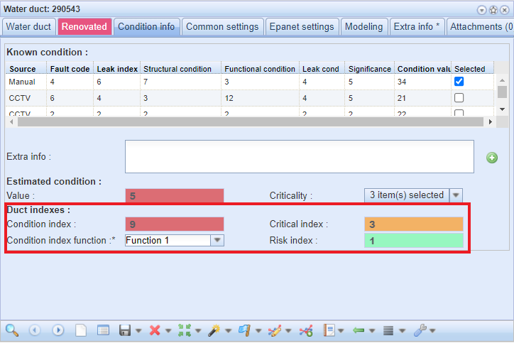
Duct indexes:
- Condition index function: Used in calculating the Condition index.
- Condition index: The value calculated using the condition index function and known condition values.
- Critical index: The number of selections in the Criticality field
- Risk index: For the Risk index there is a text constants group. The value is fetched from the Additional data field which includes a matrix table. This table calculates the data based on Condition index and Criticality index fields. If the Risk index value cannot be found it will be set to 1.
Splitting a duct
You can split water and sewer ducts with the Split tool in the drop-down menu for Modify  on the forms in question. Alternatively, you can do that when you add a node, in which case a node will be added to the splitting point and the head of the split duct will be connected to the node. The Split function is described in more detail in the chapter Splitting a line object.
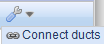
Connecting ducts
Two or more ducts can be combined into a single duct using the duct connection function. In the drop-down menu for Other tools  , select Connect ducts. Select the ducts in the order in which you want to connect them.
The following properties of the connected ducts must be the same:
- Duct type
- Material
- Diameter
- Constr. yr
- Mapper
- Survey date
- Mapping method
Other property information will be copied from the first duct. You cannot connect ducts with different network types.
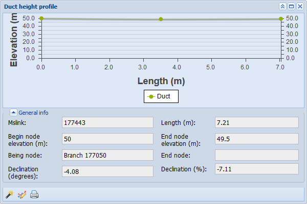
Duct height profile
The duct height profile for ducts provides lateral information on the duct’s elevation relative to the ground. You can activate this tool either on the Duct form in the drop-down menu for Other tools or by clicking Height profile  in the Common tools.
Tip! Terrain contour lines can also be added to your KeyAqua. This function is subject to a separate order.
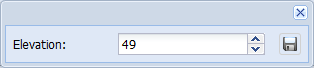
In addition, the Duct height profile  tool can be used to modify the elevation of the points of the duct. To do this, click the point of the duct
  on the curve and enter the new elevation value in the dialogue box that is displayed. You cannot use the Duct height profile tool to change the elevation of the duct’s start and end nodes, but you must make these changes on the Duct form (Open Duct
 form) or with the Node ducts and elevations tool. Duct curves can be hidden by clicking the
  text.
text.