On the Logical mass connection change form, you can implement mass connection changes to the connectors of the telecommunication network devices and related circuits.
The basic principle of this function is that you choose the telecom premises, device and connectors whose reservations you want to edit. In addition, you choose the telecom premises that are used as a replacement or added, and the device on which the changes are implemented. The device with the connectors that are used as replacements can be located either on the same telecom premises (cross-connection) or on entirely different telecom premises (logical connection), and connections can also be transferred from certain connectors to others within the same device (internal connection). The Logical mass connection change form can also be used to replace or disconnect a circuit’s connections.
A logical mass connection change can have one of the following statuses: planned, accepted, or rejected. A planned mass connection change can be edited later. An accepted mass connection change replaces the previous connections of the connectors in question with new connections, and saves the previous connection information as historical data in the database. The planned changes of a rejected logical mass connection change are removed from the database.
You can create a mass connection change report on a planned logical mass connection change in PDF or XLSX format. This report makes it possible to compare the situation with the starting point before you accept or reject a plan.
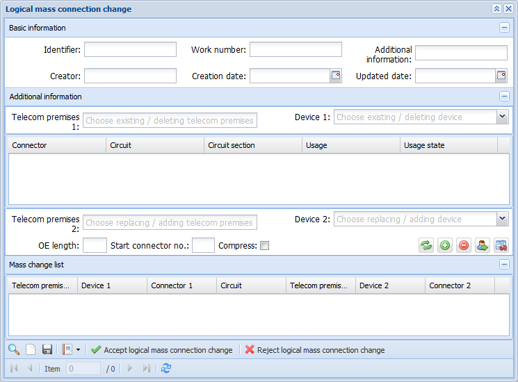
On the Basic information section, you can add an identifier, work number, and additional information. The identifier is a mandatory field and a mass connection change will not be added unless this information has been entered.
You can use the Identifier, Work number, and Additional information fields as search criteria for a logical mass connection change. You can edit the information related to a mass connection change and save changes by clicking Save.
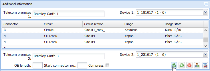
Additional information
The Telecom premises 1 (existing/deleting telecom premises) field displays the telecom premises location of the connectors that are to be modified. The search function for telecom premises is activated when you start entering text in the field. On the displayed list of search results, select the required telecom premises by clicking the left mouse button. The Telecom premises 2 (replacing/adding telecom premises) is searched in the same way.
The devices on the selected telecom premises are listed in the menu for Device 1 (existing/deleting device). The active selection in the Device 1 menu defines the content of the connector list. In the menu for Device 2 (existing/deleting device), select the replacing/adding device on the telecom premises 2.
The Connector list displays the connectors of the device that is selected in the existing/deleting device menu. Each connector is displayed on a separate row. Each connector row displays the connector name, circuit identifier, circuit section, usage, and usage state.
You can select the connectors for the logical mass connection change either all at once or one-by-one, for example, based on the circuit identifier. To select connector rows, click with the left mouse button while holding down the Ctrl or SHIFT key.
Enter the length of the new other end connection in the OE length field. In the Start connector no. field, enter the connector number from which the compressing/placement functions are started. Select the Compress checkbox to activate/deactivate the compressing function.
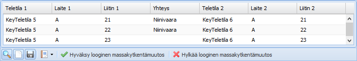
Adding changes to the logical mass change list
To add new change data to the mass change list, select the required additional information in the Additional information section of the Logical mass connection change form. Then, depending on the situation, click either Replace logical mass connection change item , Add logical mass connection change item
 , Delete logical mass connection change item
 , Replace circuit connections
 , or Cut circuit connections
 .
.
Replace logical mass connection change item
If you replace a logical mass connection change item while leaving the Start connector no. field empty and you do not select the Compress checkbox, the connectors selected in the current device will be placed on the connectors with the equivalent numbers in the replacing device.
In the example figure below, the connector 4 of Device 1 in the telecom premises Bramley Garth 1 are replaced with connector 4 of Device 2 in the telecom premises Bramley Garth 3.
In the example figure below, the mass change list displays the planned changes.
If you enter a connector number in the Start connector no. field, the connectors selected in the current device will be transferred to the replacing device using the same connector ranges as in the current device, starting from the connector that you defined as the start connector.
If you apply compressing to the replacement logical mass change that you implement, the connectors with circuits that you selected in the current device will be compressed in the replacing device in the order of available connectors and starting from the connector defined as the start connector (the order of the connectors reserved for a circuit is not necessarily the same as in the original device).
The application guides you by providing notifications if, for example, you select an already reserved connector as the starting point for compressing.
If you implement a mass change using the replacement function, and connectors with no circuits have been selected on the Connectors list, the following notification will be displayed:
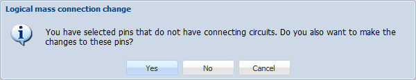
Select Yes to apply the change to all connectors selected on the connector list.
Select No to apply the change only to connectors with circuits.
Select Cancel to cancel the mass change in question.
If you implement a mass change using the compress function and connectors with no circuits have been selected on the Connectors list, the following notification will be displayed:
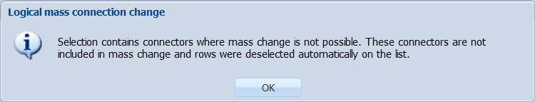
When you select Yes, the program will ask you for a confirmation: Only pins that are reserved to circuit can be changed by using compress. Do you want to continue? These connectors are not included in mass change, and rows were deselected automatically on the list. Click OK to accept the change.
Add logical mass connection change item
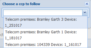
Use the Add logical mass connection change item function to connect a connector of a new replacement device (Start connector no.) to a connector in a circuit’s connection chain and to select whether the connection chain is to be continued in the same direction as in the original connection, or if the direction is to be changed. Click Choose to confirm your selection.
Delete logical mass connection change item
The connector selected on the Connector list in the Additional information section is deleted from the circuit with the Delete logical mass connection change item function.
Replace circuit connection
The Replace circuit connection function transfers circuits from the connectors of an existing device to the connectors of another existing device without disconnecting logical connections. In this case, the previous connection chain of the circuit is replaced with the route of the selected connector.
The application follows the connections of the connector selected as the replacement only in the direction of the OE connection, and it reserves the connection chain it finds for the circuit. If several logical connections are found, the process will be discontinued at the connector in question.
When you accept a logical mass connection change, the reservations of the original circuit will be deleted, and the new ones will be applied. Any unused cross-connections that remain for the original circuit will be deleted.
Cut circuit connection
The Cut circuit connection function is used to cut the circuit’s route from the connection selected for the mass connection change, and the remaining part is replaced with the connector connections that are used as replacements. In the planning phase, before accepting the change, a circuit has two circuit sections–the original and the planned route change (1 PLAN).
The replacing connector cannot contain more than one logical connection. If the replacing connector has a logical connection and a cross-connection, the cross-connection is disconnected, and the route that is defined by following the logical connection is selected as the route for the rest of the circuit.
Deleting a mass connection change item
To delete a row (and the related changes) that has been selected on the mass change list, click the right mouse button and select Cancel logical mass connection change.
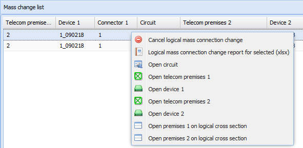
If a circuit is linked to a connector, you can also use the following functions by using the context menu on the mass connection change list: Logical mass connection change report for selected and Open circuit. The other available functions can be used to open the telecom premises and devices related to the mass connection change and open the telecom premises on a logical cross-section form.
Accepting and rejecting a logical mass connection change
To accept changes planned on the mass change list, click Accept logical mass connection change . After you have clicked this button, you will be asked to confirm that you want to accept the mass connection changes.
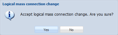
Click Yes to implement the planned changes and to remove the basic information on the logical mass connection change from the database. The original set-ups before changes are stored in history tables in the database. Click No to cancel the acceptance of changes.
To reject changes planned on the mass change list, click Reject logical mass connection change . You will be asked to confirm that you want to reject the logical mass connection changes: Click Yes to reject the planned changes and to remove the basic information on the mass connection change from the database. Click No to cancel the rejection of changes.
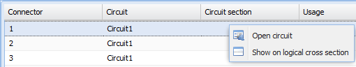
Opening a circuit on the form
To view the circuit identifiers on the Connector list or mass change list, right-click a row and select Open circuit . This function opens a Circuit form with the information on the circuit in question. Click Show on logical cross section
 to go to the Cross-sectionform.
Logical mass connection change report
You can create a Logical mass connection change report for the planned logical mass connection change. You can create a report either as a PDF or an Excel document and print or save the report for further use. Click Reports to create a report.
A logical mass connection change report provides information on both the original circuit and the planned circuit. In addition, this report includes basic information related to the mass connection change. In the report, the connection on which the planned change will have an effect is marked with the symbol * at the beginning of the change row for connections.