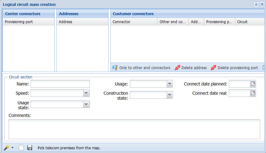
The Logical circuit mass creation form is available in the KeyNet toolbar. The purpose of the Logical circuit mass creation form is to enable easy and fast circuit mass creation, for example, for new residential areas with detached houses. This form consists of three tree-like sections: Center connectors, Addresses, and Customer connectors. In addition, the form includes Circuit section information.
Start logical circuit mass creation by defining the area, such as a new residential area, using the Pick from map function. The telecom premises and the related devices and connectors within the selected area are listed on the Connector column in the Customer connectors section.
In circuit mass creation, the automatic connection reservation is based on existing logical connections and, for this reason, the last connector in a logical connection chain is displayed in the Other end connector column. If the connector displayed in the Other end connector column is classified as a center connector, it is automatically listed in the Provisioning port column. Similarly, the address information for telecom premises that are within the selected area is listed in the Addresses section, and the center connectors on the telecom premises that are included in the Other end connector column are listed in the Center connectors column at the telecom premises, device, and connector level.
If the connectors listed in the Customer connectors section have already been reserved for circuits, these rows are marked in blue and the circuit identifier is displayed in the Circuit column. To view the information related to a circuit, activate the required row by selecting it and then click Open circuit (you can also right-click to access the Open circuit function in the context menu). The edited lines are marked in green.
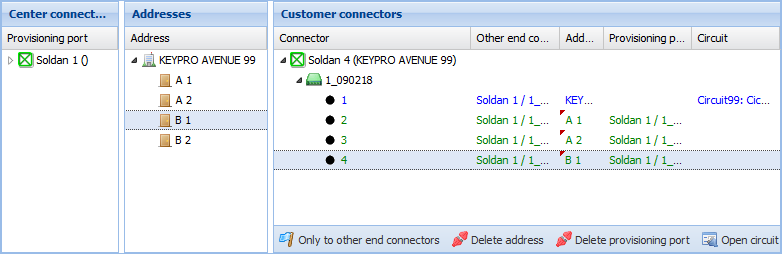
Start the circuit mass creation by dragging the addresses over to the connectors in the equivalent telecom premises either one-by-one or as a mass. If the connector at the customer end has related connections, and these connections lead to telecom premises that also provide provisioning ports, provisioning ports can also be dragged over to the equivalent customer end connector rows either one-by-one or as a mass. The dragged addresses and center connectors are displayed in the Addresses and Provisioning port columns in the Customer connectors section. Information on modified rows is marked in green.
Note! When items are dragged as a mass, dragging can only be carried out for rows that have information in the Other end connector column. Click  to activate this function.
To delete the dragged addresses and provisioning ports, select the required rows in the Customer connectors section and click either Delete address or Delete provisioning port
 . You can also activate the Delete address and Delete provisioning port functions by selecting them in the menu that is displayed when you right-click a row.
To create a new circuit, provide the appropriate basic information in the circuit section and then click Create . A new identifier is generated for the circuit, the dragged address is defined as the installation address, and the basic information fields in the section are completed with the selected information on the circuit section. Circuits are created for connectors and connection routes related to the connectors that are marked in green in the Customer connectors section. When a circuit is created, the dragged provisioning ports are automatically added at the beginning of the connection chain. After you click Create, you see a notification displaying the number of circuits and the related connectors.
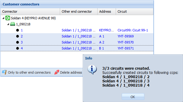
After successful circuit creation, the connectors in question will be displayed in blue in the Customer connectors section. If no active usage state has been selected in the drop-down menu for the Usage state field in the circuit section, the Logical circuit mass creation tool will create, by default, a circuit with the usage state Pre-connected when its connections extend to a provisioning port. If no provisioning port has been defined, the tool will automatically create a circuit with the usage state Partially pre-connected.