On the Connections management form, with the Logical state being selected, you can create, cancel and edit KeyNet connections. Logical connections are connections between the connectors of devices in telecom premises. The two windows (lists) of the Connections managementform display the devices in telecom premises. You can select different telecom premises to be displayed on the lists. Browse through the tree diagram to find all possible connectors and the connections below them.
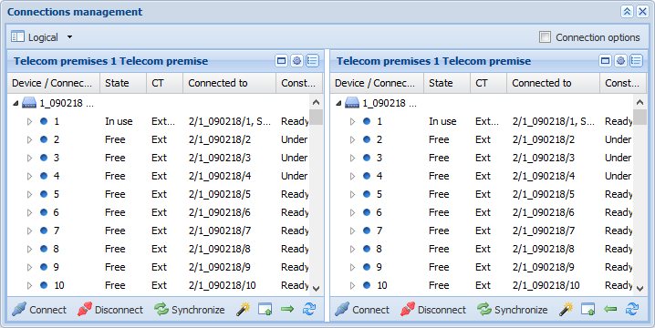
CT means connection type. The various connection types include Cross-connection (CC), Internal connections (INT), and External connections (EXT). The basic functions of this form are explained in the chapter Connections management.
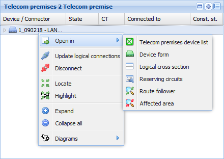
The available functions depend on whether you open the context menu (with the right mouse button) over a device, connector, or connection. From the Open in menu, you can access the Device form, Telecom premises device list, Logical cross-section, Route follower, or the Circuit form for reserving circuits. Click Affected area to open a Route follower form pre-completed with the selected device’s connectors and cables connected to the connectors. The route follower highlights the connection routes that are connected to the selected device either directly or over logical cross-connections.
In the figure below, the context menu when opened over Device.
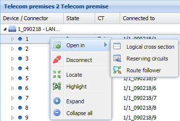
In the figure below, the context menu when opened over Connector.
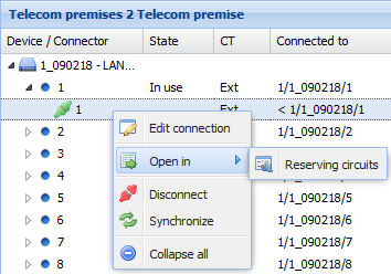
In the figure below, the context menu when opened over Connection.
Internal connections
If you want to create internal connections, click Copy telecom premises to left  /right
 . The devices of the telecom premises in question are then also displayed on the other list, after which you can create internal connections in the same way as other connections (see the chapter Creating connections).
Connection options
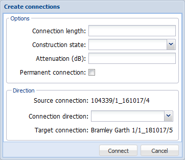
When creating logical connections, you can define the connection length, construction state, attenuation (dB) and create a permanent connection, as well as define the direction of the connection. First, select the Connection options checkbox in the top-right corner of the Connections management form.
Editing a logical connection
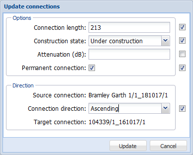
Edit the logical connection by selecting Edit connection in the context menu that is displayed when you click the right mouse button. When you make changes, the checkbox to the right of a field is selected and the Update button is activated. Click Update to accept the changes. You can cancel any changes by deselecting the checkbox for the field before you click Update.
In addition, the following functions are available, when you click the right mouse button over a connection: Open in – Reserving circuits, Disconnect, Synchronize, and Expand/Collapse all.
Filtering the displayed logical connections on the form
- Click Filter
 .
. - Enter/select filters.
- Click Update in the Filter window.
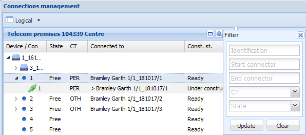
To remove filters, either click Clear filter or first click Filter
 , then click the Clear button and after that click Update.
Viewing reserving circuits
- Select the row for which you want to view the reserving circuits.
- In the context menu, select Open in – Reserving circuits
 to open the Circuit form with the reserving circuits displayed. If there are no reserving circuits, the Circuit form will not be opened, and the following text will be displayed in the bottom left corner of the KeyCom window: Selected is not reserved by any circuits.
Updating the logical connections of a device
- Position the mouse pointer over a device, click the right mouse button and select Update logical connections
 .
. - In the dialogue box displayed, select the checkbox if you want to delete existing logical connections. Do not select the checkbox if you want to create the required connections while maintaining the existing ones.
- After the connections have been created, the number of created logical connections will be displayed.
- Note! Logical connections can also be updated automatically. This is discussed in more detail in the Update logical connections automatically chapter.
Route follower for managing logical connections
Position the mouse pointer over a device, click the right mouse button and select Open in Route follower . The Route follower form is opened with the selected device displayed. If your mouse pointer is positioned over a connector and you use the right mouse button to select Route follower
 , the form is opened with one connector displayed. More information on Route follower is provided in the chapter Route follower.