Select one of the available options to go to the Route follower form to view a route you created:
- In the KeyCom tools menu, click Route follower
 .
. - On the Cable form, go to the Tools
 menu and select Route follower or Thread details. On the displayed Threads for cable form, click the right mouse button to access the Route follower.
 - On the Device
 form, in the Tools
 menu, select Route follower.
 - Go to the Devices tab of the Telecom premises
 form, click the right mouse button over the device row, and select Follow route in the context menu.
 - On the Service area
 form, click Create
 to access the route follower options.
 - Click the physical or logical reservation rows on the Circuit form or use the Reserve connection drop-down menu.
- On the Connections management
 form, click a cable or device with the right mouse button.
 - Click a device or connector row on the Logical cross-section form.
Initiate Route follower
Start following using an empty Route followerform by using the Pick object tool. After you have downloaded the object used for starting the route following to a form, information on the object will be displayed after the text Follow. If you have entered the Route follower form via the Device or Cable form, the element in question will automatically be the object that is followed.
Route following can be used, for example, to locate the affected area of a device in the event of an incident or fault situation. The Distance tool can be used to define the exact cable location in metres.
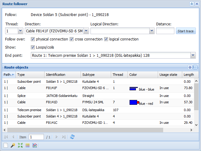
Define the criteria for the route follower
On the Route followerform, you can define the criteria according to which the route following is carried out:
- In the Thread field, you can define the thread or device connector that is followed. You can select more than one thread or connector by holding down the Shift or Control key.
- In the Direction field, you have the option to define the direction for following in accordance with the physical network. This field also allows multiple selections.
- In the optional Logical direction field, you can define whether the direction of logical connections is ascending or descending.
- In the Distance field, you can define the maximum distance (in metres) to be applied to route following starting from its starting point. The Route objects list displays the End point row, which can be used to locate the defined route length marked on the map by a red cross. This function is useful, for example, when locating faults.
- Follow over – physical connection: Following continues over existing physical connections.
- Follow over – cross connection: Following continues over the device’s cross-connections.
- Follow over – logical connection: Following continues over existing logical connections.
- Show – Loops/coils: This selection displays the loops/coils and their lengths in the Route objects list.
- The End point menu lets you select all routes or a single route to be displayed in the Route objects list.
- Click Start trace to start route following. The located routes and their objects are displayed in the Route objects list.
Route follower results
The route follower results are listed in the Route objects view.
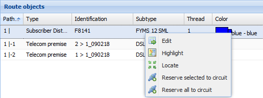
Click a route row with the right mouse button to access the menu through which you can edit the selected object by clicking Edit . Click Highlight
 to highlight an object on the map. Click Locate
 to center the map on the route and to highlight the route on the map. If you want to reserve route objects for a circuit, use the Reserve selected to circuit
 or Reserve all to circuit
 functions. Further information on these functions is available in the chapter Connection reservations for a circuit.
You can add and remove displayed columns by clicking located on the right. The displayed menu lets you define the information content of the column.
You can browse the route follower results by using the arrow buttons at the bottom.
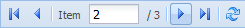
The first page of Route objects displays all the followed routes. The subsequent pages display the located routes in the order: route 1, route 2 etc. If Distance has been defined for the route, the route options with their end points are displayed from page 2 onwards.
Viewing route follower results in group display
You can view the results of route following in the group display by clicking Show components of the route in group display . Further information on the group display is available in the chapter Group display.
Attenuation diagram
You can create an illustrative Attenuation diagram from the route follower results. Click Attenuation diagram
 on the required page for route follower results. The displayed Attenuation diagram window illustrates the attenuation (dB) of the network elements and their connections on the Y-axis and the distance from start (m) on the X-axis.
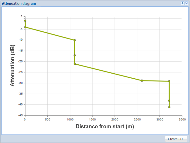
Click Create PDF to create a PDF report on the attenuation diagram. The Attenuation report includes the attenuation diagram and the route follower results in accordance with the selected columns.
Creating a buffer area from the route follower
You can create a buffer area based on the results of route following. Instructions for buffer area creation are included in the chapter discussing Service areas: A new buffer area from route follower.