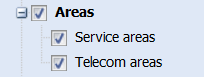
Click Service areas to open the form for managing service areas. You can search for service areas based on search criteria or pick their information from the map and, for example, locate them on the map. The Service areas layer is not selected by default in the Layers selection.
Creating a service area
Define a name and category for the area on the Service area form together with any comments you may have.

You can create an area in the same way as you create other area objects. Click the left mouse button to define the area’s points and click the right mouse button to stop drawing. You can define the shape of the Service area by using the functions available under Create : Create point buffer and Create line buffer. Creating point and line buffers is discussed in the chapter Adding an area.

The Service areas object layer is automatically activated in the layer selection when you create a new service area Zoom the map to see the names of the areas.
New service area from telecom premises
You can also define a service area automatically in the Create new menu. A service area can be created based on, for example, telecom premises.
Retrieve the telecom premises to the Telecom premises form. The area creation uses it for service creation. The telecom premises are used as the starting point for area creation.
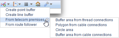
Circle area from telecom premises
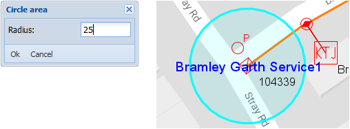
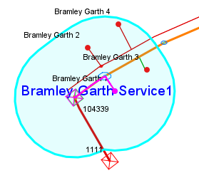
In the telecom premises menu, select Circle area to create a circle around the telecom premises retrieved to the telecom premises form. Create the area by defining its radius (in metres) as illustrated in the figure below.
Buffer area from thread connections
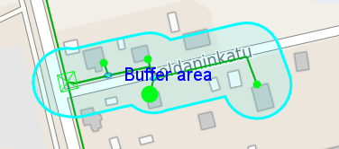
Buffer area from thread connections creates an area originating from the selected telecom premises by following the cables along the cable level connections. The following does not require pair-level connections. To create the service area, define the maximum distance for following the cable network and define the width of the buffer area to be created (metres).
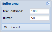
The cable network will be followed for the defined maximum distance. When the maximum distance is reached at some branch, the previously found telecom premises will be used for defining the area. The branches found using this method form a sausage-like area, where the buffer defines the width of the service area over the cables.
Buffer area from cable connections
The functions of the Buffer area from cable connections option are otherwise identical to those of the Buffer area from thread connections, but the following is carried out based on pair-level connections and cross-connections between devices. The use of this function requires network connections to have been documented in detail.
Polygon from cable connections
As is the case with the Buffer area, the Polygon from cable connections option is based on following cables through thread-level connections. This function uses the telecom premises located through following in order to create a polygon that covers all the telecom premises that were located.
A new buffer area from route follower
You also have the option to create a service area based on the results of the route follower.
- Name the service area, for example, “Buffer area from route follower”.
- In the drop-down menu for Create
 , select From route follower and then click Buffer area.
 - On the Route follower form, specify the device or cable to be used for following a route.
- On the Route follower form, select Create buffer area based on the route follower results
 . You can cancel the creation of a buffer area by clicking Cancel creating of buffer area
 .
. - Define the buffer distance in metres in the Buffer dialogue box that is displayed. Click OK.
- A buffer area has now been created on the map based on the route follower results. (Do not forget to activate Areas in Layers)
A new polygon service area from the route follower
You can create a polygon service area based on the results of the route follower.
- Enter a name for the service area.
- In the drop-down menu for Create
 , select From route follower and then click Polygon.
 - On the Route follower form, specify the device or cable to be used for following a route.
- On the Route follower form, select Create buffer area based on the route follower results
 . You can cancel the creation of a buffer area by clicking Cancel creating of buffer area
 .
. - A polygon service area has now been created on the map based on the route follower results. (Do not forget to activate Areas in Layers)
Viewing a service area in a group display
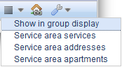
In the drop-down menu for List , select Show in group display to view the service area in a group display.
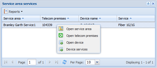
Service area services
In the drop-down menu for List , select Service area services.
In the context menu for the Service area services, you can open the service area in question, the related telecom premises and device, and the services related to the device.
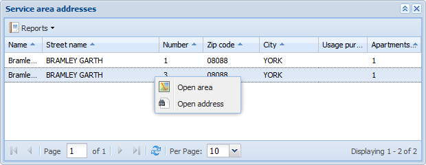
Service area addresses
To list the addresses located in the service area , go to the drop-down menu for List and select Service area addresses. The form that is displayed is equivalent to the form’s List function that is discussed in the chapter List.
Use the context menu for Service area addresses to go to the service area and address in question.
Feeding premises
You can view the feeding premises of the service area from the Feeding premises tab. In the title of the tab, the number of feeding premises is indicated in parentheses, which is updated when new telecom premises are added or deleted.
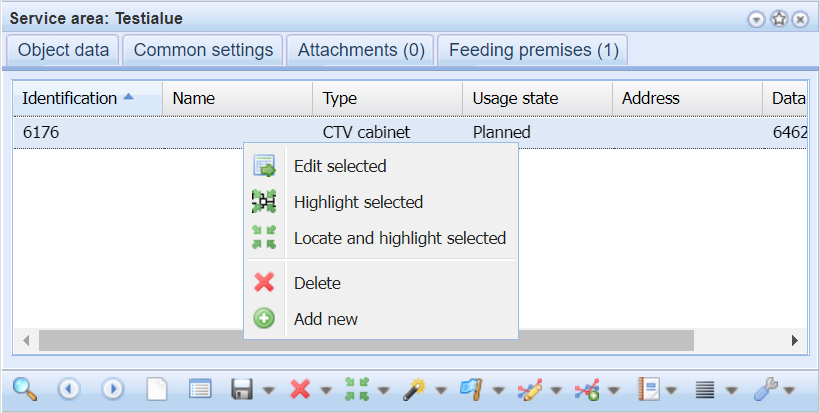
You can manage the Feeding premises from their context menu. Right click on the grid to open a menu. You can edit telecom premises with their own forms, zoom and highlight telecom premises on the map and delete and add new feeding premises to the service area.
Adding and deleting feeding premises
- Start adding a new feeding premise by clicking the Add new
 button in the context menu.
 - Search or add the necessary information on the Telecom premises
 form and click the Export to form
 button from the toolbar.
 - Telecom premises can then be found in the Feeding premises tab.
- Remove the telecom premises with the Delete
 button in the context menu if you need to.