Telecom premises information
In KeyCom, the telecom premises object refers to a point object that may be connected to equipment and cables. In addition, house cabinets and manholes are typically also considered telecom premises. The basic functions of the telecom premises form are the same as those used for managing other point objects. More information on the basic functions is provided in chapter Buttons on object forms.
The Telecom premisesform includes the field Manhole diagram confirmed. In the drop-down menu, select Yes/No according to the situation. If this field is empty, no action has been taken regarding the manhole diagram related to this manhole.
The number of circuits that are used and connected to the telecom premises is displayed on the Telecom premisesform in the Active circuits field.
The Technical info field is for documenting detailed technical information related to the telecom premises. For example, you may want to mention that the telecom premises are located on top of a hill or in a basement.
The importance classification is determined in accordance with the guidelines provided by Traficom (Finnish Transport and Communications Agency). Components that belong to a public communications network or a communication service are classified according to type, geographic scope, and number of users. The importance classification ranges from 1 to 5. The more important a service is, the higher the number. The importance classification of telecom premises is determined based on the component with the highest importance classification.
The principles for moving telecom premises are mainly the same as those described in chapter Modifying the geometry of a point object. Select Modify , and when the Move: connected checkbox is checked, any cables, conduits, annotations, splices, and other telecom premises connected to it are also moved with the telecom premises. If you check the Connect checkbox, the telecom premises object will be connected to a manhole/pole/premises when it is modified. Information on the connection is then displayed in the Manhole/Pole/Premises field on the Telecom premisesform. You can later choose the manhole/pole/premises on the map by selecting Connect to manhole/pole/premises in the drop-down menu for Manhole/Pole/Premises.
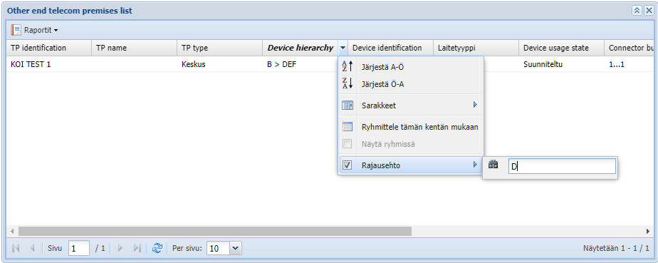
Other end telecom premises list
In the Other end telecom premises list, you can generate other end telecom premises information by selecting a device with possible sub-devices. The information on the list consists of the logical other end connections between the connectors of the devices located in the selected telecom premises. Each other end connection, which leads to consecutive connectors of the same other end telecom premises, is presented as a separate row on the Other end telecom premise list.
The Other end telecom premises list can be used to find the right device in large telecom premises, for example, in cases where you only know the address of the other end telecom premises and you want to know the device and the connector that leads to the desired other end telecom premises with other end connections.
The Other end telecom premises list can be opened from the context menu that opens above the selected device from the Cross-section, Telecom premises, Device and Connection management forms by clicking Open Other end telecom premises list. In addition, the form can be opened for all devices in a telecom premises from the drop-down menu of the List function of the Telecom premises form's toolbar by clicking the Other end list button.

The columns of the Other end telecom premises list
By default, the information presented in the counterpart status list is presented in the same way as in the device list of the Cross-section form. The list does not show those devices that do not have connectors, such as switchboards or device racks. The logical counterpoint bundles related to the devices' connectors are presented in the list in the order in which they are formed, including the devices' successive connectors and their counterpoint connections.
- TP identification
- TP name
- TP type (column hidden by default)
- TP address
- TP address postal code and post office (column hidden by default)
- TP address municipality (column hidden by default)
- TP comment (column hidden by default)
- TP technical info (column hidden by default)
- Device hierarchy (for example, parent devices of a fiber panel, "A > B > C")
- Device identification
- Device type
- Device class (column hidden by default)
- Device usage state
- Connector bundle (identifier of the first and last connector of the connector bundle, separated by three dots, e.g. "1-2-3-14...1-2-7-85")
- Length (the length of the logical other end connection in meters)
- Free (the number of free connectors in a single bundle like shown on the Cross-section form)
- OE TP identification
- OE TP name
- OE TP type (column hidden by default)
- OE TP address
- OE TP address postal code and post office (column hidden by default)
- OE TP address municipality (column hidden by default)
- OE TP comment (column hidden by default)
- OE TP technical info (column hidden by default)
- OE device hierarchy (column hidden by default)
- OE device identification (column hidden by default)
- OE device type (column hidden by default)
- OE device class (column hidden by default)
- OE device usage state (column hidden by default)
- OE device connector bundle (identifier of the first and last connector of the bundle separated by three dots, e.g. "1-2-3-14...1-2-7-85") (column Hidden by default)
- Device id (column hidden by default)
- OE device id (column hidden by default)
Filtering on Other end telecom premises list
The information in the Other end telecom premises list can be filtered in the columns. The user can choose to display in the list, for example, only the connector bundles leading to the desired address of the other end telecom premises according to free text filtering. The column header is highlighted if it is subject to a separate filtering condition.
Other end telecom premises list context menu functions
With the functions of the context menu, you can switch to viewing the device selected from the other end telecom premises list and the connections of the connected bundle in other forms.
- Open in cross section form
 : synchronize the first connector of the selected device and connector group and opens the Cross-section form
 - Open in telecom premises device list
 : synchronize the selected device and the first connector in the bundle and opens the Devices tab.
 - Open in connections management form
 : synchronizes the selected device and the first connector in the group and opens the Connections management form.
 - Open in telecom premises form: opens the Telecom premisesform with the telecom premises and other end telecom premises data.
- Open in device form
 : opens the Deviceform with the device and other end information.
 - Open in address form
 : open the Addressform with the address and other end telecom premises address information.
 - Edit connection
 : opens the Edit connectionsform, from which the logical connections related to the connector bundle can be updated at once for all logical other end connections.
Creating telecom premises
You can create new telecom premises by providing the mandatory information: Type and Usage state. It is not mandatory to place the premises on the map. The program automatically creates an Identification number for the object by applying consecutive numbering.

Moving telecom premises
The principles for moving telecom premises are mainly the same as those described in the chapter Modifying the geometry of a point object. Select Modify , and when the Move: connected checkbox is selected, the cables, conduits, annotations, splices and other telecom premises connected to it are also moved with the telecom premises. By selecting the Connect checkbox, the telecom premises object will be connected to a manhole/pole/premises when it is modified. Information on the connection is then displayed in the Manhole/Pole/Premises field on the Telecom premisesform. You can choose the manhole/pole/premises from the map afterwards by selecting Connect to manhole/pole/premises in the drop-down menu for Manhole/Pole/Premises.

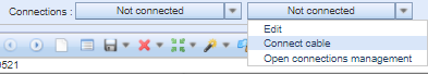
Connecting to a cable
On the Cable form, in the drop-down menu for Connections, select Connect cable to connect telecom premises to a cable. On the map, use your mouse to define an area by using the Pick
 tool in order to select the manhole or pole to be used for the connection. If the area includes more than one network element, select the correct object by double-clicking it on the Object selection list. The cable will then be connected to the selected object. You can also create the connection by clicking the network element with the right mouse button and selecting Connect to cable. If the connection succeeds, the following text will be displayed on the form: Cable connected successfully, and the name of the network object appears in the Connections menu.
Devices
You can view the devices and services of telecom premises on the Telecom premises form’s Devices tab. When a device has been selected, its information is displayed at the bottom of the form. In addition, there is a separate button for Devices and device groups in the KeyCom tools.
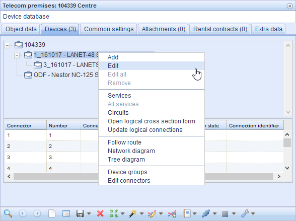
The Devices tab of telecom premises displays a list of the telecom premises on top and its devices in a tree-like list under it. Use the plus and minus signs to view and hide the devices on the telecom premises in question. You can view more detailed information on a device by clicking it with the left mouse button. Information on the device’s connectors are then displayed at the bottom of the object form. The tab’s header indicates the number of devices connected to the telecom premises in parenthesis, for example Devices (6).
Via the KeyCom admin interface, you can filter device types based on device class.
The Device list menu on the Telecom premises form includes the following functions (click the right mouse button over the device row):
- Add for adding a new device (opens a device form with the selected device as the parent device). For more information: Adding a device to telecom premises.
- Edit for editing device information. More information is available in the chapter Editing a device.
- Edit all for editing the information on all devices on the telecom premises. More information: Mass update (Update all).
- Remove for removing a device. More information is available in the chapter Removing a device from telecom premises.
- Services for defining the services provided by the device’s ports. More information: Services.
- All services for viewing the services provided by all the devices on the telecom premises in question. More information is provided in the chapter Services.
- Circuits for viewing the circuits that use the connections of the selected device. More information is provided in the chapter List of circuits on the telecom premises.
- Open logical cross-section form for viewing a device’s logical connections and circuit reservations. More information is provided in the chapter Logical cross-section.
- Create logical connections for updating the logical connections of the selected device connections by following cable connections. More information is provided in the chapter Update logical connections.
- Route follower for activating route following from the selected device. Further information is provided in the chapter Route follower.
- Affected area opens a Route follower form pre-completed with the selected device’s connectors and cables connected to the connectors. The route follower highlights the connection routes that are connected to the selected device either directly or over logical cross-connections.
- Network diagram for presenting the connections of the selected device in a network diagram. More information is provided in the chapter Diagrams.
- Tree diagram for presenting the connections of the selected device in a tree diagram. More information is provided in the chapter Tree diagram.
- Device groups for managing device groups (a group of devices with their connectors and connections. More information is provided in the chapter Device groups.
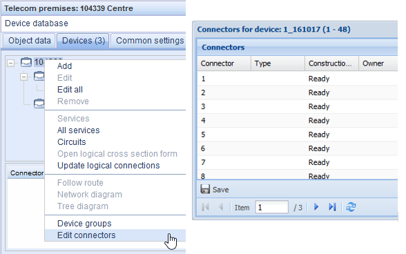
- Edit connectors for managing the connectors of a device. More information is provided in the chapter Managing connectors.
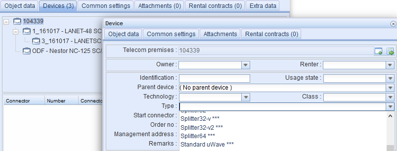
Adding a device to telecom premises
On the Devices tab, select the Telecom premises or an existing Device for which you want to add a sub-device.
- Click the right mouse button to open the device list menu and select Add to open the Device
 form.
form. - Enter the property values. Device Type is a mandatory field.
- Click Save form
 to add the new device to the selected telecom premises.
You can also use the Device form to add all the devices of the device group at once, including their connectors and the internal connections of the telecom premises. In the drop-down menu for Type, device groups have been marked with ***. More information is provided in the chapter Device groups.
On the Device form, you can also edit a device’s connectors, create diagrams, follow routes, add tasks related to a device, monitor the change history of a device and open the Cross-section
 form.
form.
You can retrieve devices to the Device form, for example, based on existing areas. From the drop-down menu for Pick
 , select one of the following three functions: Map view area, Free area, or Existing area.
You can also create a copy of an existing device by selecting Save as copy in the drop-down menu for the Save form button. The device’s connectors and their properties are then also copied.
Removing a device from telecom premises
- Select the device you want to remove from the device list for the telecom premises.
- Select the correct object on the list and click the right mouse button. Select Remove.
- Confirm the removal to remove the device in question.
If you remove a device to which sub-devices are connected, these devices are also removed at the same time. However, the deletion of hierarchical devices is prevented if the set of devices includes, for example, customer circuit reservations or other dependencies related to database integrity.
The removal of the parent device and related sub-devices must be confirmed in a separate confirmation window related to device removal. The user is informed in detail in those situations where removing the devices is not possible.
Note! If the device’s connector or connection has been reserved for a Circuit (see the Circuits chapter), you cannot remove the connector or device. If you want to remove such a device, you must first edit the connections reserved for the circuits so that no connectors of the device are reserved for circuits.
Editing a device
- On the device list, select the device you want to edit.
- In the drop-down menu for the device list, select Edit to open the Device
 form that includes the information on the device in question.
 - Edit the information you want to change.
- Click Save form
 .
.
You can automatically place an added or edited device on the Devices list on the Telecom premises form. Select the Parent device on the list to add the device under it. Please note that you must first retrieve the correct Telecom premises to the Device
 form.
form.
For the lower half of the Device form, you can document the physical location of the devices to the Area, Rack Row, Rack, Side, Subrack, Slot and Sub slot fields. The fields can also be activated in the Logical reservations table on the Circuit
 form from the Columns menu, which can be opened by clicking on one of the already activated columns. These columns can also be activated on the Connection management
 form.
form.
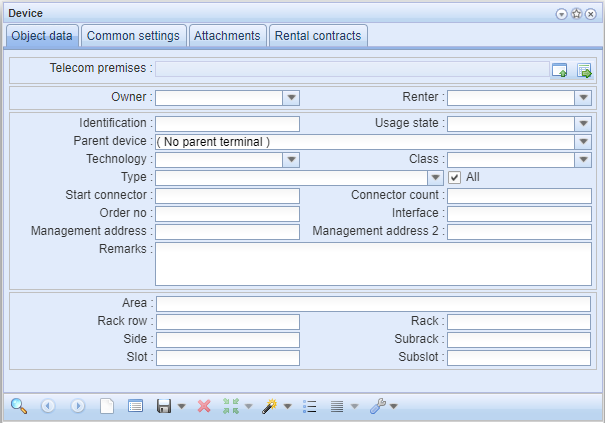
Note! You can view CATV devices but editing options have been limited: you cannot edit the Technology, Class, Type, Start connector and Connector count values.
Copy a device to telecom premises
- Select the device you want to copy and open it for editing, as described in points 1–2 in Editing a device.
- Retrieve or pick to the Device
 form the telecom premises you want to copy the device to.
 - On the Device form, in the drop-down menu for Save form
 , click Save as copy.
 - The device has now been copied to the telecom premises and its connectors have the same identifiers as the copied device.
Moving a device to other telecom premises
- Select the device you want to move and open it for editing, as described in points 1–2 in Editing a device.
- Retrieve or pick to the Device
 form the telecom premises you want to move the device to.
 - On the Device form, click Save form
 .
. - The system asks you to confirm the move (and the moving of cables if cables have been connected to the device). When you confirm it, the device is moved to the new telecom premises.
Open from the Telecom premises form
Open the Devices tab on the Telecom premises form by clicking Show telecom premises in form
 button. The form opens directly to the Devices tab, where you can see the telecom premises and the devices connected to it in a tree-like list. The device opened from the Device
 form in question is highlighted in the list.
Update logical connections
- On the device list, select a device or telecom premises depending on where you want to update the logical connections.
- In the drop-down menu for the device list, select Update logical connections.
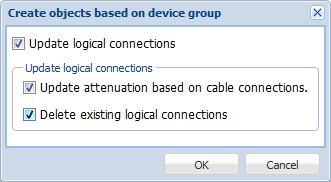
- Select the applicable logical connections and click OK in the displayed dialogue box when the system wants you to confirm whether the existing logical connections should be deleted and attenuation updated based on cable connections.
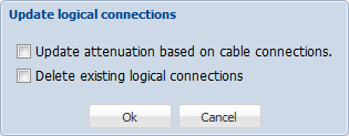
Make a note of the number of updated logical connections and click OK.

Logical connections are discussed in the chapter Connections management (logical).
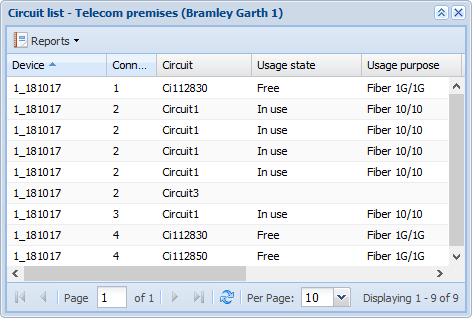
List of circuits on the telecom premises
The list of circuits on the telecom premises includes all circuits of the telecom premises or the circuits of a device and the sub-devices under it in the device hierarchy.
- Open the Devices tab.
- With the mouse pointer positioned over either telecom premises or a device, select Circuits from the context menu for the device list.
The list of circuits is a list view. More information is available in the chapter List. Circuits are introduced in the chapter Circuits.
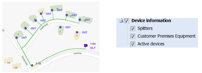
Device information on the map
Device information is available as a separate layer, with the sub-layers Splitters, Customer Premises Equipment, and Active devices. The device classes and device types are classified by admin users through the admin user interface. The abbreviation for the device type is displayed on the network map.
Device groups
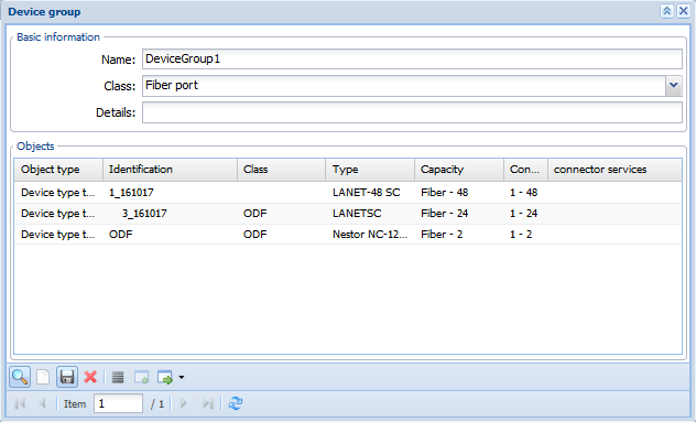
A device group is a set of devices, their connectors and the connections between the connectors. With device groups, you can harmonise the device documentation and decrease the effort required for creating new device premises. For example, you can create standard equipment set-ups for various network nodes, such as the Fiber subscriber (an ODF panel and the optical active device) or Fiber Optical distribution box (ODF Panels and PON Splitters including the device-internal connections and cross connections between the devices).
 is available in the KeyCom toolbar, in the drop-down menu for Device. You can also access the Device group form from the Telecom premises form’s Devices tab by clicking Device group in the context menu for the device list. You can use the Device group form to create, edit and view device groups. You can also view the Device groups on the Device
 form in the same way as you view any other device types. The only difference is that, in the menu for Type, the Type of device groups is marked with ***
Create a Device group by providing the group a Name, Class, and Details. Then click the Save button on the Device group form. This creates a new device group of the devices, connectors and their cross-connections that are active on the Telecom premises form. Note that when you create a device group, it must be linked to some telecom premises. To do this, click Pick from telecom premises form when the required telecom premises object has been retrieved to the form.
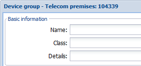
In the example figure below, a device group that is linked to the telecom premises ”104339”.
In the example figure below, a new device group, DeviceGroup1, has been created on the Device group form.
To edit a device group’s name, class, and details, edit the property information and then click Save. You can edit the information on the devices that belong to a device group only by creating a new device group. Click Delete to delete a device group.
You can add a device group’s devices to telecom premises through either the Device form or Device group form.
Adding devices to telecom premises through the Device group form:
- To start adding the devices of a device group to telecom premises, retrieve the telecom premises to which you want to add the device group’s devices to the Telecom premises form.
- Open the Device group form and retrieve the information on the device group you want to add.
- On the Device group form, click Create devices to telecom premises
 . The devices of the selected device group will then be added to the telecom premises displayed on the Telecom premises form.
Note! You can add the same device group to several telecom premises at the same time. In the drop-down menu for Create devices to telecom premises , click Create devices to all telecom premises. You will be asked to confirm the adding of the device group to all the telecom premises on the telecom premises form. Confirm in order to add the device group to the telecom premises on the form.
Support for automatic cable connections is enabled for the device group devices. Automatic connections are created based on the cable role, and the connection data for cables and splices is created on the new telecom premises with the devices.
Managing connectors
The property values and mass naming of Connectors are managed through a separate form that displays the connectors of the selected device and the properties of the connectors, such as connector, type, construction state, owner, speed, details, and priority. To open the Connectors for device form, go to the Device
 object form and click Edit connectors
 or select Edit connectors in the pop-up menu for the device list. When you select Edit connectors in the pop-up menu, you can browse through all the device connectors on the telecom premises one device at a time.
The connector number column is hidden by default. You can activate it in the drop-down menu for columns by ticking the Columns – Number checkbox.
You can also open the Connectors for device form through the connector list for Devices by selecting connectors and using the right mouse button to open a pop-up menu with the option Edit connectors. This opens the Connectors for device form for the selected connectors. Note that the displayed form may be empty if other filters are applied to the form. More information on the filters: Using filters for connectors.
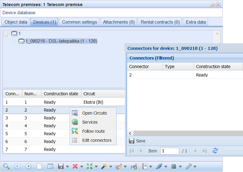
On the Connectors list, you can also click Open circuits to open the Circuit form with information on the connector’s circuit. The form has no pre-completed information if no connector has been reserved for the circuit.
Services opens the Services: Device
 form pre-completed with information on the device. You can add the service type information for the connector.
Follow route can be selected by clicking a connector row with the right mouse button. This opens the Route follower form with information on the thread in question.
Editing connectors
You can edit the property values of the connectors on the list either individually or as a group.
To edit a single property value of a connector, double-click the cell on the list and update the property value. Click Save to accept the change. To cancel the changes before saving, click Refresh
 on the form.
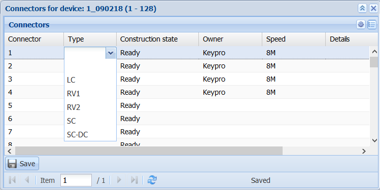
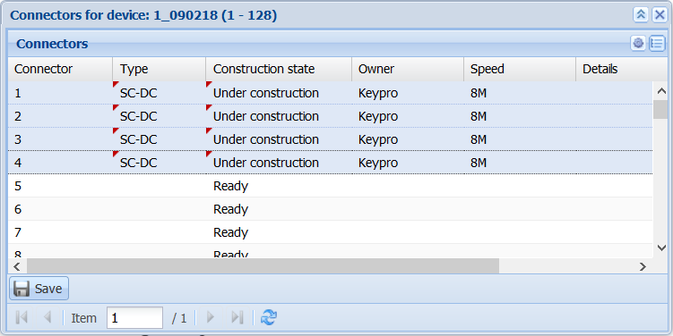
To edit several connectors at the same time, select the required connector rows using the left mouse button while holding down the Ctrl or SHIFT key. In the pop-up menu available by clicking the right mouse button, select Edit selected. Update the required property values for the selected group of connectors.

Note! Names within a device must be unique. The naming of a connector group is discussed in the chapter Naming a connector group.
Click Update on the sub-form to confirm the changes. Data that has not been saved is marked with a small red triangle. On the Connector form, click Save
 to save your changes.
Naming a connector group
Start naming a set of connectors either in the same way as you would edit several connectors, or use the right mouse button to view the context menu and select Rename selected or Rename all. Naturally, you can also rename individual connectors.
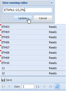
Naming is carried out based on naming rules. The basic format is the following:
%
for example,
%1:6,2+2%
returns the names
01, 03, 05.
Table 1. Naming rules for a connector group.
LP1- | A standard text that is applied to all connectors |
%1:10% | A running number sequence, where the first connector receives the value 1, the second 2, etc. |
%1:10%-%1:10% | Two running number sequences. Numbering starts with 1-1, 1-2…1-10, after which 2-1, 2-2…2-10, 3-1, 3-2, etc. |
%1:10,2% | Otherwise same as above, but two numbers are used (01, 02, etc.) |
%1:10,2+2% | As above, but 2 is always added to the previous figure. In other words, the numbers produced are 01, 03, 05, 07, and 09 |
Within the % characters, the parameter sequence is the following:
- Defining the running series range (1:10)
- Optional zero padding (,2)
- Optional stepping +2
Names are only given to as many connectors as the rules can create. In this case, the first three connectors at the most. If more connectors have been selected, the rest of them are not named.
The basic format can be used with other characters and for multiple times,
for example,
a%1:6,2+2%-b%1:3,2%
creates nine names:
a01-b01, a01-b02, a01-b03,
a03-b01, a03-b02, a03-b03,
a05-b01, a05-b02, a05-b03.
Enter the naming rule in the text field and update the connector list with the names created based on the rule by clicking Update. Click Save to accept the changes. To cancel the changes before saving, click Refresh
 on the form.
Note! When filters are applied, the Rename all function only renames the filtered group.
Using filters for connectors
To open the filters, click Filters in the top-right corner of the form.
In the example figure below, filtering a connector list based on name, start and end connector, type, construction state, owner, bit rate, details, or priority.
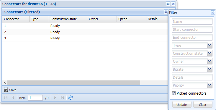
Enter the filters or select them in the drop-down menu. Click Update to accept them. The connector list is updated and only the filtered connectors are displayed. The filters remain valid when you open the form for another device or view some other device by clicking the navigation buttons on the connector form. The Clear button for filters clears the filters, but it does not remove them from the form until you click Update.
The filters for connectors are applied when the Connector for device form has been opened for the selected connectors.
To clear the filters, click Clear filter in the top-right corner of the form.
Services
To open a new Services for device form through the Devices tab , click the right mouse button over a device. Then select Services. The form lists all the services for the device in question. Broadband is one example of services. You can also open the Services form through the connector menu by using the right mouse button to select the required connector row.

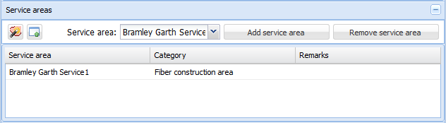
The sections in the Services for device form are the following: basic information, service areas related to the device, addresses, and service type’s connectors. You can add services by clicking Add. Then choose the correct Service type and enter Remarks if necessary. The Service areas and Addresses fields are activated when you use the left mouse button to select an added service type on the list. Click Update to save the service. Click Remove to remove the service. These functions also have the option Update all and Remove all.

After this, in the drop-down menu, select Service area and Address.
Click Pick service area to add a service area to the drop-down menu for Area. Another way to retrieve the information from the Service area form is to click Pick from service area form
 . Note that the correct Service area form must be open in the KeyCom environment.
If you use the Pick service area tool, the Service areas layer must be active in the layer selection. Point at the required service area with the left mouse button, or define several areas on the map while holding down the left mouse button. The selected area/areas appear in the Service area menu, and you can then use them for the service.
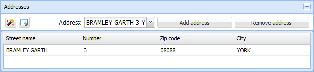
Pick addresses functions in the same way as the Pick service area tool. Add the required addresses to the drop-down menu for Address by clicking an address on the map with the left mouse button. The Addresses layer must be active in the layer selection. Because addresses are small point objects, it is easier to select the required address on the map if you define an area on the map while holding down the left mouse button. The address/addresses found appear in the Address menu, and you can then use them for the service.
Information can be retrieved from the Address form by clicking Pick from address form . Note that the correct Address form must be open in the KeyCom environment.
To list the services for all the devices on the telecom premises, go to the Devices tab of the telecom premises, select All services in the context menu for the telecom premises. A list of the services for all the devices on the telecom premises is then displayed.

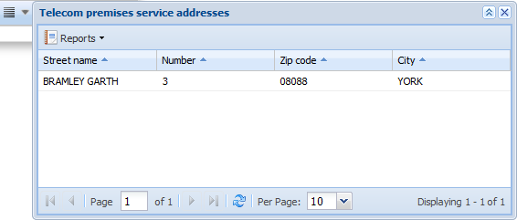
To view the service addresses related to the telecom premises, click the drop-down menu for List and select Telecom premises service addresses. The addresses linked to the telecom premises services are listed at an apartment level. You can print a report of the list in Excel format.
Device database
The Device database menu on the Telecom premises form is available only for users that belong to the DeviceDB_Access group. Click the Device database button on the Telecom premises form to open forms that are related to the telecom premises. These forms are used, for example, for editing information related to masts, air conditioning, antennas, and contact persons.
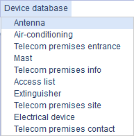
Most of the property attributes on forms are form-specific. The forms are introduced in the appendix Device database forms. You can use the form functions in the same way as the functions of other forms, but the number of functions is limited: you can search, update, and delete information.
In the example figure below, one of the device database forms, an Access list, you can use search criteria to search for information, and you can update or delete information.
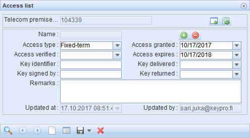
In addition to the form functions, the common denominator for all forms is that a form must be linked to telecom premises. To do this, click Pick telecom premises from telecom form . The ID of the telecom premises on the Telecom premises form then appears on the form. If no telecom premises information has been retrieved to the Telecom premises form, you cannot link the form. Click Show telecom premises
 to open the object form of the telecom premises in question and to view its information. The Updated at and Updated by dates will automatically appear on all forms when information is saved in the database by clicking Save form
 .
.
On some Device database forms, you can add information on the customer, rental contract, and address by clicking .
.
Use search criteria to search information that is already stored in a database. For example, if you want to retrieve customer information to the Access list form, click to open the Customer form. Enter the customer’s information in the Name field and click Search
 . If there are several results, use the arrow buttons
 to browse through them in order to find the correct customer. Click Update to form
 to add the information to the object form. To save the retrieved information on the object form, click Save form
 . Click Clear
 to clear the information from the form.
To view the list of objects related to the customer, click List related objects on the Customer form. The list includes the type and name of the objects. Click the right mouse button over the target row to access the Show on the form button. This takes you to the object form.
Telecom premises report
To create a telecom premises report, click Reports  and then select Telecom premises report. You can choose whether to create an Excel table or a PDF of the devices on the telecom premises and the object in the device database.

On the telecom premises report form, you can create an Excel report on the devices and extra features of the telecom premises.