The various selection lists of the application forms are retrieved from the text constants. If the content of the text constants is edited, the selection lists on the forms will be changed accordingly the next time the application is downloaded.
Editing text constants
Click the Text constants link in the admin interface.

On the displayed list, click the ID of a text constant to edit it. To limit the list content to a single group, click the group in question on the Filter list.
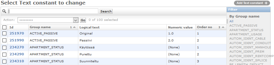
Text constant columns
Text constants include the following information for each setting:
- Group name: text constants have been divided into groups, which are used to categorise the settings related to various topics.
- Logical text: the text that the application uses internally.
- Text [fi]…Text [en]: the translations of the Text field that are displayed in the browser in the selected language.
- Numeric value: is used, for example, as the numeric value equivalent to the text value, to provide information on whether the object is included in the safe-to-dig.com service, whether the feature is in use and to indicate the type of technology. Further information is available in the chapter that discusses each specific group.
- Abbreviation: the internally used default abbreviation of the text constant.
- Abbreviation [fi]...Abbreviation [en]: the translations of the Abbreviation field that are displayed in the browser in the selected language. If the selected language is not supported, the Abbreviation field will be displayed.
- Numeric value 2…Numeric value 4:
- Numeric value 3: Is used for existing *_OWNER groups to point directly to STP Owner ID, which will be then used directly in the STP view (Environment/Customer specific STP Owner ID's to be defined manually per environment when STP activation happens). With this, it is important that these fields remain free until then.
- Text value: varies depending on the group. As a rule, this is not in use.
Category: not in use.
- Description:
- Value…Value 4: these fields are usually related to the description techniques of old systems. You can ignore these fields if you are using the browser application.
Optional data
- Order no: a sequence number for settings. For example, if the values of a group are retrieved for a selection list, the values will be displayed in the order specified by the order number. For some groups, values with negative order numbers are not displayed on the selection lists.
- Availability start and end:displayed/can be modified through the group’s own admin interface if the field is in use. If data has been entered in these fields, selections with availability start or end dates in conflict with the current date (not available anymore or availability period has not yet started) will be displayed either in grey or not at all depending on the group.
Deleting text constants.
Text constants can be deleted from the list of text constants. Make sure that the text constants you delete are not used anywhere else in the application. To delete text constant, select one or more text constants from the list and choose the "Delete constant(s) with no check" action, then approve the deletion. If any of text constants are used anywhere in the application, the deletion will fail.
Common text constants
Login screen terms
The terms and conditions link available in the login screen is defined in the TERMS_AND_CONDITIONS group under Text constants. To activate the link in the login screen fill in the following fields:
- Group name: TERMS_AND_CONDITIONS
- Logical text (TXT): private_terms
- Order number: 1 (order number)
- Text value: Link of for the terms and conditions. For example, “https://www.company.com/terms_and_conditions”.
- Text [fi]: Yksityiset ehdot (the value that is visible to the user)
- Text [en]: Private terms (the value shown to the user on the English login page)
- Text [sv]: Private villkor (the value that is displayed to the user on the login page in Swedish)
Placement scale
The placement scales available in the map tools are defined in the SCALE group under Text constants.
- Text…Text (en): a scale value that is appropriate for the user, for example, “1:500”.
- Numeric value: the numeric value equivalent to the text for scaling objects.
- Value: not available in the browser application. A reference to a Feature table. Contact Keypro’s application support for help.
- Value 2: not available in the browser application. A reference to a Feature table. Contact Keypro’s application support for help.
- Numeric value 2: defines the default placement scale. The default placement scale when the application is launched is a placement scale with a Numeric value 2 = 1.
Location accuracy and height accuracy
Location accuracies are defined in the LOCATION_ACCURACY group, while the H_ACCURACY group is used to define height accuracies. Both are used on some of the object forms in the relevant selection lists on the Common settings tab.
- Text…Text (en): text specifying the location accuracy, for example, “+-5 m”
- Numeric value: a numeric value equivalent to the text field, for example, 5.0. The value in this field is the radius of a circle in metres, within which the actual location of an object is when measured from the object’s saved location and at the applied level of certainty.
Plan state
The state of a plan is defined in the PLAN_STATE group.
- Numeric value 2: if the state of a plan is changed to “ready”, the user will be asked whether the usage states of the related objects should be updated (they will be updated to a usage state with the numeric value 1 (see Usage state)
0 | not displayed in the safe-to-dig.com service |
1 | ready, with planned objects also being displayed in the safe-to-dig.com service |
null/<something else> | planned objects will also be displayed in the safe-to-dig.com service |
If the Numeric value 2 is not zero or NULL, the plan-related objects with the usage state “planned” will be displayed in the safe-to-dig.com service. (Objects with the usage state “in use” are always displayed in the safe-to-dig.com service, regardless of the plan’s state.) This means that it is possible to specify, for example, that objects linked to plans that are in the pre-planning phase or under planning are not displayed in the safe-to-dig.com service. If a planned object is not linked to any plans, it will be displayed in the safe-to-dig.com service.
- Text value: Locks the objects in the plan if the Maintenance state of plan objects feature is enabled. See the Maintenance state of plan objects (O&M) chapter.
1 | editing of objects with the usage state “In use” is not allowed |
<something else> | the objects in the plan can be freely modified |
Maintenance state of plan objects (O&M)
The maintenance state of the plan objects locks the objects in the plan with the state “In use” and prevents the editing of the objects (a notification is displayed to the user). Only the users in the O&M user group (OM_PLAN_ADMIN) have the right to change the state of the plan to something else than the O&M state. The O&M state is defined using the text value of the plan. See the Plan state chapter. The following objects are supported:
- Cable
- Conduit
- Duct
- Telecom premises
- Device
- Splice
- Manhole
- Pole
- Points objects
- Connections at the cable and device level
- Circuit sections
Plan type
The plan type is defined in the PLAN_TYPE group.
Numeric value: defines the type of plan in question
4 | Deconstruction |
If the plan’s type is deconstruction and the plan’s usage state is changed to ready (see the Plan state chapter), the user will be asked whether the objects related to the plan should be deleted or scrapped. If the user selects deletion, the objects will be deleted. If the user selects scrapping, the usage state of the objects will be changed to a state (see Usage state) with a numeric value of 3. This feature is activated with the setting PLAN_AUTOMATIC_SCRAPPINGS.
Point object types
Name: name that the application uses internally.
Label [fi]…Label [en]: localised name that is visible to users.
Symbol name: the symbol that is displayed on the map.
Point object type category: the category that the type belongs to. See the Point object type categories chapter.
Point object type categories
The type categories of point objects are defined in the POINT_TYPE_CATEGORY group.
- Logical text: the text that the application uses internally
Loop/coil | a point object linked to a cable |
<other> | a regular point object |
- Text [fi]…Text [en]: the translations of the Text field that are displayed in the browser in the selected language.
- Numeric value: the type of the category
1 | a category used as redline in Keymobile |
-1 | Types used in KeyRNS. The trigger updates the type_id data field for the object. The type_id field will be removed, but its fields are still used by safe-to-dig.com and the placement scale calculation (An obsolete group of point object types). |
Point object defaults
To set the defaults, go to a Point object form in the application and click Save as defaults in the drop-down menu for Save. The selection is only visible to admin users.
Address usage purposes
The usage purposes of addresses are defined in the APARTMENT_USAGE group (the usage purpose of an apartment) and the BUILDING_USAGE group (the usage purpose of a building).
- Numeric value...numeric value 4: these fields specify the addresses that will be excluded in various situations, for example, if you do not want to include addresses with the usage state “Demolished”. If no value has been entered or the value entered into the field is 0, the address will be included. Otherwise the address will not be included. Addresses are displayed in accordance with the table below.
Numeric value | 1 | Related to external interfaces. Do not edit! |
Numeric value 2 | 1 | Related to external interfaces. Do not edit. |
Numeric value 3 | 1-11 | The VRK usage code equivalent to the purpose of use. (Note! Only used in Finland.) This is used when the VRK material is used to update addresses. Do not edit. |
Numeric value 4 | 1 | Addresses are not updated directly from the VRK file, but the update is included in the list of addresses that will not be updated. (Note! Only used in Finland.) |
- Text value: The Text value of the BUILDING_USAGE group specifies the color of the address symbol.
r g b | Color of the address symbol. Each value is a number between 0...255, for example, green is presented as “0 255 0”. |
Address usage purpose 2
The values for the Address usage purpose 2 field are defined in the KN_ADDR_SPEC group.
- Numeric value: Numeric value defines if the address is filtered out in automatic address search and in TTMi-interface’s address search.
1 | Address is filtered out in automatic address search and in TTMi-interface’s address search. |
Other | Address is not filtered. |
- Text value: The text value defines the color used to display the address number on the map.
r g b | The color of the address number. Each value is a number between 0...255, for example, green is presented as “0 255 0”. |
Address defaults
To set the defaults, go to an Address form in the application and click Save as defaults in the drop-down menu for Save. The selection is only visible to admin users.
Address and apartment data
This group will include information of available source systems (3rd party companies/systems) which will add address and apartment data to KeyCom.
To define the Source system and Source system key options that are displayed to users under the Common settings tab on the object forms, go to the SOURCE_SYSTEM groups under Text constants.
- Abbreviation: Add the wanted system name to the field.
Coordinate system options
To define the Coordinate system options that are displayed to users, go to the KEYCORE_IMPORT_SRS groups under Text constants.
- Text value: the code equivalent to the coordinate system. This code must be included in the code column of the Coordinate systems. See Coordinate systems.
Note! The KEYCORE_IMPORT_SRS group of text constants determines the options that are displayed to the user. The corresponding information must be available in the coordinate system specifications (see the Coordinate systems chapter.
Area types
Area types are defined in the FREEAREA_TYPE group.
- Numeric value: defines the area type
1 | Access restriction area |
2 | Province |
3 | City |
4 | Zip code |
5 | Switching center area (Censal) |
6 | Country border |
7 | Population center |
8 | Autonomous area (Comunidad Autónoma) |
9 | Building |
22 | Unsubsidised area |
101 | (reserved for a modified right of use area) |
Area categories
Area categories are defined in the FREEAREA_CATEGORY group. The Links of text constants chapter provides information on linking area types to categories.
Links of text constants
- Parent id: Area category (see Area categories).
- Child id: Area type (see Area types).
Usage states of areas
The usage states of areas are defined in the FREEAREA_STATE group.
- Numeric value:
102 | (reserved for a modified right of use area) |
103 | (reserved for a modified right of use area) |
104 | (reserved for a modified right of use area) |
External map links
The external map links are defined in the EXTERNAL_MAP_LINK group. The link can be opened in the Google maps drop-down menu from Map tools.
- Group name: EXTERNAL_MAP_LINK
- Logical text: the text that the application uses internally
- Order no: define the map link order in the drop-down menu
- Additional data: the map link url
- Text…Text (en): name of the external map link and the translation of the name
Traficom STP default values
The group TRAFICOM_STP_DEFAULT contains all default values for STP specific views.
NUM_VALUE column contains the default values for linestring objects and NUM_VALUE2 column for point objects.
Groupname | TXT | NUM_VALUE | NUM_VALUE2 |
TRAFICOM_STP_DEFAULT | LOCATION_ACCURACY_XY | 50 | 50 |
TRAFICOM_STP_DEFAULT | LOCATION_ACCURACY_Z | 5 | 5 |
TRAFICOM_STP_DEFAULT | PLANNED_DEPTH | 0.7 | 0.7 |
TRAFICOM_STP_DEFAULT | MAP_AREA | 50 | 50 |
TRAFICOM_STP_DEFAULT | MARKING_AREA | 10 | 0 |
TRAFICOM_STP_DEFAULT | OWNER | NULL | NULL |
Setics STTAR values of the customizable preview layer
The CUSTOM_STTAR_PREVIEW group contains all the necessary values for the customizable Setics STTAR preview layer. The text constant defines the name of the abbreviation displayed in the preview level, the text displayed on the STTAR server form and the path displayed in the context menu for activating the level.
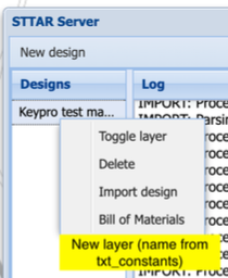
When the txt_constants row has been defined system will add a new button in the context menu with the “Toggle layer” option. The button will be labeled as what’s defined in the Text and Abbreviation fields.
- Group name: CUSTOM_STTAR_PREVIEW
- TXT: Custom Setics STTAR preview
- Numeric value: 1
- Order no: (1). If there is more than one layer, add the following numbers in order.
- Text: Add the same text to the Text and Abbreviation fields.
When making the new design, system will create a new layer which is defined by the txt_constant. The layer will be labeled with the original layer name and suffixed by the abbreviation in the txt_constant row with the design ID in the end (e.g. CW).
Note! The new layer will be available only for new designs that are created after the feature has been enabled in the system.
KeyCom text constants
Usage state
Names of groups used to define the usage state of an object end with “_STATE”.
- Numeric value: the field value is the usage state, as clarified below.
1 | In use |
2 | Planned |
3 | Discarded |
4 | Decommissioned |
<other value> | The safe-to-dig.com service assumes that the state is “In use”, but does not display it on the map |
The automatic state changing in the system will only apply to the numeric values listed above. Groups using this feature include the following:
CABLE_STATE | Usage state of a cable |
CONDUIT_STATE | Usage state of a conduit |
DUCT_STATE | Usage state of a duct |
MANHOLE_STATE | Usage state of a manhole |
POINT_STATE | Usage state of a point object |
POLE_STATE | Usage state of a pole |
PREM_STATE | Usage state of telecom premises |
SERVICE_STATE | Usage state of a service |
SPLICE_STATE | Usage state of a splice |
TERMINAL_STATE | Usage state of a terminal |
THR_CONN_STATE | Usage state of a thread connection |
Note: Usage state must have a numeric value so that it can be used on forms to mass update items.
- Numeric value 2:
Group | Numeric value | Text |
PREM_STATE | 1 | If the PREM_STATE of the telecom premise in question has a value of 1, the devices under it are also updated to that usage state. |
Technology
Technology means the technology of cables and devices (such as fiber, copper and coaxial), which determine whether the objects using a certain technology can be connected to objects using a different technology.
- Numeric value: The following groups are used to define the technologies, and the table below presents the values equivalent to each technology:
Group | Numeric value | Text |
CABLE_TECHNOLOGY | -1 | Cable TV |
CABLE_TECHNOLOGY | 0 | Copper |
CABLE_TECHNOLOGY | 1 | Fiber |
CABLE_TECHNOLOGY | (null) | Hybrid |
TERMINAL_TECH | 1 | Fiber |
TERMINAL_TECH | (null) | Hybrid |
TERMINAL_TECH | 1 | Cable TV_Fiber |
TERMINAL_TECH | -1 | Cable TV_Coaxial |
TERMINAL_TECH | 0 | Copper |
Devices/cables using hybrid technology can be connected to all other devices/cables using the same technology or some other technology. Other devices/cables can only be connected to devices/cables using the same technology or having the same Numeric value.
- Numeric value 2: CABLE_TECHNOLOGY group num_value 2 indicates the voltage of the cable.
Numeric value | Meaning |
1 | Low voltage cable |
2 | Medium voltage cable |
3 | High voltage cable |
Thread type
In KeyCom’s thread details window, you can select the thread type of each thread through the THREAD_TYPE group under TXT_CONSTANTS.
- Numeric value: defines the technology.
1 | Fiber |
0 | Copper |
null | Not defined |
- Numeric value 2: indicates the default attenuation (dB/km).
The uniqueness and NULL value of object identifiers
A rule for an identifier’s uniqueness and NULL value can be defined for each usage state of telecom premises, manholes, splices, poles, conduits and cables.
For telecom premises, the rule has been saved in the PREM_ID_RULE group, for manholes in the MANHOLE_ID_RULE group, for splices in the SPLICE_ID_RULE group and for cables in the CABLE_ID_RULE group (see Automatic generation of object identifiers).
- Numeric value: The actual setting has been saved in this field as an integer with three digits in the form of xyz. The functions of the digits are as follows:
x defines the object usage state to which the rule is applied. The available values are:
1 – In use
2 – Planned
3 – Discarded
y defines the uniqueness rule for the objects in the usage state in question
1 – The uniqueness of an object identifier is not checked at all. One identifier can occur in a database table more than once.
2 – One identifier can occur in a database table more than once, but in certain sub-areas only once.
3 – One identifier can occur in a database table only once.
z defines whether or not the identifier of the usage state in question can be null.
1 – The identifier can be null. If the identifier is null, the uniqueness of an object identifier will not be checked.
2 – The identifier cannot be null.
For example, a row in the PREM_ID_RULE group with the numeric value of 122 specifies that only one object with the same identifier can be available to telecom premises within one sub-area. Empty identifiers are not permitted for objects with the usage state “In use”.
Automatic generation of object identifiers
Automatic generation of identifiers can be defined for telecom premises, manholes, splices and cables. The automatic generation of identifiers depends on the identifier’s rule for nullability (see the Uniqueness and NULL value of object identifiers).
If the rule defines that the identifier cannot be empty, an identifier will be automatically generated in accordance with the rules for the object that is to be added or updated, unless the user enters an identifier on the form.
The settings can be found in the following groups:
Telecom premises | AUTOM_IDENT_PREM |
Manhole | AUTOM_IDENT_MANHOLE |
Splice | AUTOM_IDENT_SPLICE |
Cable | AUTOM_IDENT_CABLE |
The rules are defined as follows:
- Numeric value: specifies whether the automatic generation of identifiers has been enabled.
1 | generation enabled |
Other values | generation disabled |
- Logical text: this field contains the text that is entered for the identifier. It is entered as strings which will be replaced with the object’s actual data. Strings that will be replaced include the following:
%AREA% | sub-area |
%TYPE_ABR%, | the abbreviation of telecom premises, a splice or manhole if available. |
%TYPE% | object type |
%TECH% | the abbreviation of the applicable cable technology, or the cable technology if an abbreviation has not been defined. |
| %ROLE% | the abbreviation of the cable role, or the cable role if an abbreviation has not been defined. |
%SEQ% | a running number that is read from the following sequences: |
If the string that is to be replaced is followed by $n$, in which n is a number, the identifier will include as many digits as the number specifies. For example, if the text includes the string %AREA%$3$, the identifier will include the three first digits of the sub-area.
If a %SEQ% string ends with $n$, the ending defines the minimum number of digits that will be included in the running number. if the running number has less digits than the specified value, the number will be preceded by the required number of zeros. For example, %SEQ%$4$ generates a four-digit number such as 0015.
For example, an AUTOM_IDENT_PREM group with the text %AREA%$3$_%SEQ%$4$ will generate a telecom premises identifier such as PEH_0001.
Thread connection type
Thread connection type is defined in the THR_CONN_TYPE group.
- Numeric value: Field specifies the type of the thread connection in question.
1 | Straight |
2 | Fusion |
Duct owners
The duct owners are defined in the DUCT_OWNER group.
- Numeric value: the field specifies whether the ducts of the owner in question are included in the safe-to-dig.com service. This information is a rough equivalent of the obligation to display the duct:
1 or NULL | is displayed on the operator’s safe-to-dig.com cable maps |
0 | is not displayed on the operator’s safe-to-dig.com cable maps |
0.5 | is displayed on the operator’s safe-to-dig.com cable maps with the annotation “other operator’s cable” |
Duct connection type
The type of the duct connection is defined in the DUCT_CONNECTION group.
- Numeric value: this field indicates the type of the duct connection to be used for importing FiberPlanIT files:
1 | used as the duct connection type when importing FiberPlanIT material. If no type has been specified, the download will fail. |
Cable and thread owners
The owners of cables are defined in the CABLE_OWNER group.
- Numeric value: the field specifies whether the cables of the owner in question are included in the safe-to-dig.com service. This information is a rough equivalent of the obligation to display the cable/duct:
1 or NULL | is displayed on the operator’s safe-to-dig.com cable maps |
0 | is not displayed on the operator’s safe-to-dig.com cable maps |
0.5 | is displayed on the operator’s safe-to-dig.com cable maps with the annotation “other operator’s cable” |
1 | (own) thread is included in the cable’s capacity |
0 | thread is not included in the cable’s capacity |
- Numeric value 4: Own cable (KPI report).
1 | own cable |
Parties having the right to use threads
The parties having the right to use threads are defined in the RIGHT_OF_USE group.
- Numeric value 2: whether the thread is included in the cable’s capacity.
1 | (own) thread is included in the cable’s capacity |
0 | thread is not included in the cable’s capacity |
Cable roles and default importance
A cable’s role from the perspective of network structure is defined in the CABLE_ROLE group.
- Numeric value: this field is used for identifying the cable’s role when FiberPlanIT files are imported. If a group includes several rows having the same Numeric value, the import will be performed by using the row with the smallest sequence number (FiberPlanIT is a service subject to a separate order).
Numeric value 2: the field specifies the cable’s default importance category if the Importance field is empty.
Role | Importance | Numeric value | Numeric value 2 |
Drop cable | A drop cable from the customer’s location to the first flexibility point | 1 | 1 |
Distribution cable | A cable that connects the first and second flexibility points of the network (the first and second points from the customer’s location) | 4 | 2 |
Feeder cable | A cable that connects the exchange to the first flexibility point (the first one from the exchange) | 5 | 4 |
Transmission cable | A cable that connects exchanges | 2 | 5 |
Transmission + subscriber cable | A cable with both transmission and customer circuits | 3 | 5 |
Numeric value 3: specifies whether the capacity theme is applied when the cable is displayed
1 | the capacity theme is applied when the cable is displayed |
0/null | the capacity theme is not applied when the cable is displayed |
Cable importance
The Cable form includes a Cable importance field that defines the primary cable importance. The field’s value must be between 0 (not important) and 5 (very important).
If this value has not been defined, the default importance related to the cable’s role will be used (see the Duct connection type chapter).
Extra lengths of cables
The extra length of a cable models the cable’s bends as it traverses across the terrain and inside ducts.
The extra length is defined in the KEYCOM_EXTRA_LENGTH group.
Numeric value: the extra length as a percentage of the total length of the line on the map and the included loops/coils, for example, 0.04 adds 4% to the cable’s total length.
Provisioning devices
Device categories (DEVICE group) with Numeric value 2 = 1 are classified as provisioning devices (see Device type class). Provisioning devices are used, for example, for reserving provisioning ports for circuits and in the tool for circuit mass creation.
Defining cable capacity
Maximum capacity:
- The numeric value 3 for the cable owner = 1
- The numeric value 2 for the thread owner = 1 or the numeric value 2 for the party having the right to use the thread = 1 (see Cable and thread owners and Parties having the right to use threads)
Connected capacity:
- The numeric value 2 for thread construction = 1 (see Circuit and thread construction state)
- The numeric value 2 for the thread owner = 1 or the numeric value 2 for the party having the right to use the thread = 1 (see Cable and thread owners and Parties having the right to use threads)
Used capacity:
- The numeric value 2 for thread construction = 1 (see Circuit and thread construction state)
- The numeric value 2 for thread usage state = 1 (see Usage state of threads)
- The numeric value 2 for the thread owner = 1 or the numeric value 2 for the party having the right to use the thread = 1 (see Cable and thread owners and Parties having the right to use threads)
Free capacity:
- The numeric value 2 for thread construction = 1 (see Circuit and thread construction state)
- The numeric value 2 = null for the thread usage state
- The numeric value 2 for the thread owner = 1 or the numeric value 2 for the party having the right to use the thread = 1 (see Cable and thread owners and Parties having the right to use threads)
Usage state of threads
The usage state of threads is defined in the KN_USAGE_STATE group (see Usage state of circuits).
Preventing the editing of threads
The editing of threads that are in use can be prevented through the settings of the KN_THREAD_CHANGE group. The group can only include one row.
- Numeric value: the action taken if a user attempts to edit a thread that is in use:
0 | editing is not allowed |
1 | editing is allowed, but a warning is displayed |
2 | editing is allowed |
Circuit usage purpose
The usage purposes of circuits are defined in the USAGE group.
Text [fi]…Text [en]: the usage purpose and the related translation displayed to the user.
- Numeric value 2: Determining the circuit name.
1 | The circuit name will consist of the abbreviation of the usage purpose and a running number sequence (the sequence name must be defined in the Description field). |
- Numeric value 3: Status of the circuit section.
0 | POINT-TO-POINT (P2P) |
1 | POINT-TO-MULTIPOINT (P2MP). The completion of a circuit does not change the usage state or construction state. |
- Numeric value 4: Status of OTDR monitoring.
0 | Monitoring for circuit is off |
1 | Circuit is being monitored |
- Description: name of the number sequence used in the circuit’s name.
For example, TEL12345 is the result of the following definition in the USAGE group:
Text | Abbreviation | Numeric value 2 | Description |
Telephone | TEL | 1 | SQ_TEL_SEQ |
An obsolete group of point object types
The current editing method for point objects is described in the Point object types chapter.
Note: New functionalities must not be dependent on the type_id field of the point_object table or on the POINT_TYPE group!
Users are no longer using the POINT_TYPE group themselves in the KeyCom application, and the type_id field for point objects is filled in by using a trigger in the database and originally for the purpose of keyrns, but some other functions also continue to be dependent on this field.
- Logical text:
Loop/coil | Is displayed in the safe-to-dig.com service if the numeric value so states. |
<any value> | Is not displayed in the safe-to-dig.com service. |
- Numeric value: the field specifies whether the object type in question is displayed in the safe-to-dig.com service.
0 | not displayed |
1 | displayed |
- Numeric value 2: the field specifies whether the route’s installation type is buried or aerial
NULL/0 | Buried |
Negative | Shallow depth, estimated depth in metres, for example, -0.2 |
1 | Aerial |
- Value, Value 2, Value 3: specifies the multiplier for the placement scale. The multiplier is selected based on the numeric value of the usage state by using a trigger.
States of rental contracts
The states of rental contracts are defined in the RENT_STATUS group.
- Numeric value:
0 | Free |
1 | Reserved |
2 | Rented |
- Numeric value 3:
1 | <reserved> |
4 | <reserved> |
2 | <reserved> |
- Numeric value 4:
1 | <reserved> |
5 | <reserved> |
Customer types
Customer types can be defined in the KN_CUST_TYPE group. The existing customer types are listed below. The numeric value specifies the customer type:
Group | Numeric value | Description |
KN_CUST_TYPE | 1 | Private person |
KN_CUST_TYPE | 2 | Company |
KN_CUST_TYPE | 3 | Private–restricted |
KN_CUST_TYPE | 4 | Fault notification |
Route following direction
Logical directions used when following a route are defined in KN_CONN_DIR group.
Group | Numeric value | Description |
KN_CONN_DIR | 1 | Ascending direction |
KN_CONN_DIR | 2 | Descending direction |
Line type
Line type is determined in text context FREE_LINE_TYPE.
- Numeroarvo:
1 | Redline. Type which can be created in KeyMobile. It’s used in field palnningSitä käytetään kenttäsuunnittelussa. |
2 | Kadun keskiviiva. Tyyppi, jota käytetään kun viivoja viedään kadun keskiviivoiksi automaattisissa suunnittelutyökaluissa (Setics STTAR ja Comsof FPI) |
Type category of the external document
External document type is defined in the group EXT_DOC_CATEGORY.
- Numeric value 2:
External document which uses this type of category cannot be deleted by the user. |
KeyNet text constants
Usage state of circuits
The usage state of circuits is defined in the KN_USAGE_STATE group. This group is also used to define the usage states of cable threads.
- Numeric value: must be unambiguous and the values 1–6 must be included in the database.
KPI reports: the value 21 means that the thread in question is reserved. - Logical text: the text that the application uses internally. See the KeyNet’s circuit colors chapter for equivalencies.
- Text [fi]… Text [en]: presents the value in a localised user-friendly format.
- Numeric value 2: specifies whether the state in question is deemed to be an “in use” state when calculating the cable capacity.
1 | is deemed to be in use for the purposes of cable capacity calculations (the typical values include the following: 2, 3, 4, 7, 8) |
0 | not included in capacity calculations |
- Numeric value 3: specifies the usage states of sections that will be included in the Automatic circuit reservation processing. For further information, see chapter Automatic processing of circuit reservations (cron job).
Circuit and thread construction state
The construction state of circuits is defined in the KN_CONST_STATE group. This group is also used to define the usage states of cable threads.
- Numeric value: must be unambiguous and the values 1–7 must be included in the database.
- Logical text: the text that the application uses internally.
- Text (fi)…Text (en): presents the value in a localised, user-friendly format. See the KeyNet’s circuit colors chapter for equivalencies.
- Numeric value 2: specifies whether the state in question is deemed to be “ready” for the purposes of capacity calculations, i.e. ready for circuit reservation.
1 | is deemed to be ready for the purposes of cable capacity calculations |
0 | not ready for the purposes of capacity calculations |
KeyNet’s circuit colors
The states of circuits that are presented on KeyNet’s logical cross-section forms are defined in the KN_USAGE_STATE and KN_CONST_STATE groups.
The color of a circuit is defined as follows:
- By the circuit’s usage state (KN_USAGE_STATE)
- By the circuit´s construction state (KN_CONST_STATE)
The colors of the background and text are defined separately in the Description field, with the “;” character as a separator.
For example, r255g255b255;r0g0b0 means black text on a white background, and r0g0b255;r255g255b255 means white text on a blue background.
Group | Numeric value | Description | Text |
KN_USAGE_STATE | 1 | r255g255b255;r0g0b0 | Free |
KN_USAGE_STATE | 2 | r152g255b152;r0g0b0 | In use |
KN_USAGE_STATE | 3 | r255g255b0;r150g150b150 | Soon free |
KN_USAGE_STATE | 4 | r255g246b143;r0g0b0 | Soon in use |
KN_USAGE_STATE | 5 | r100g149b237;r0g0b0 | Pre-connected |
KN_USAGE_STATE | 6 | r151g255b255;r0g0b0 | Partially pre-connected |
KN_USAGE_STATE | 7 | r238g210b238;r0g0b0 | Ready to be connected |
KN_USAGE_STATE | 8 | r189g252b201;r150g150b150 | Soon closed |
KN_USAGE_STATE | 9 | r189g252b201;r0g0b0 | Closed |
KN_USAGE_STATE | 10 | r250g200b150;r0g0b0 | Backup |
KN_CONST_STATE | 1 | r240g240b240;r0g0b0 | Ready |
KN_CONST_STATE | 2 | r190g190b190;r45g0b0 | Planned |
KN_CONST_STATE | 3 | r207g90b48;r0g0b0 | Broken |
KN_CONST_STATE | 4 | r150g150b150;r0g0b25 | Under construction |
KN_CONST_STATE | 5 | r150g0b0;r0g0b0 | Deleted |
KN_CONST_STATE | 6 | r150g150b0;r0g0b0 | Tech. reservation |
KN_CONST_STATE | 7 | r0g150b150;r0g0b0 | Unbuilt |
30 | r150g0b0;r255g255b255 | Fiber fault detected | |
KN_CONST_STATE | 40 | r255g127b0;r0g0b0 | Fiber repair in progress |
KeyNet’s circuit fault colors
The states of circuit faults that are presented on KeyNet’s circuit fault forms are defined in the CIRCUIT_LOG_STATE group.
The colors of the background and text are defined separately in the Description field, with the “;” character as a separator.
For example, #00FF00;#000000 means black text on a green background.
Group | Orderno | Description | Text |
CIRCUIT_LOG_STATE | 1 | #00FF00;#000000 | Ready |
CIRCUIT_LOG_STATE | 2 | #FF0000;#000000 | Informed |
CIRCUIT_LOG_STATE | 3 | #FFFF00;#000000 | Under work |
Types of circuit installation addresses
The types of circuit installation addresses are defined in the KN_LOCATION_TYPE group. The various types include the following: “Beginning”, “Beginning corner address”, “End” and “Corner address at end”.
- Logical text: “Beginning”, “Beginning corner address”, “End” and “Corner address at end”
- Numeric value 2: the Automatic provisioning port reservation function processes the address types for which this field has the value 1. If the value of this field is empty (= null) for all the circuit installation address types, the automatic provisioning port reservation function will process all address types.
Circuits’ organisations
The organisations for circuits are defined in the KN_ORGANISATION group.
- Logical text: name of the organisation for the application’s internal use.
- Text [fi]…Text [en]: translations of the organisation’s name that are displayed in the browser in the selected language.
Generating circuit identifiers
The automatic generation of circuit identifiers is defined in the KN_CIRCUIT_ID group.
- Logical text: the format to be used is entered into the field, for example “CIR-%ID%”, so that if an identifier is missing, one will be created automatically by using the circuit’s internal key (e.g. CIR-121314).
The following values can be used when defining an identifier:
Attribute | Purpose |
%ID% | Internal key |
%YYYY% | Current year (e.g. 2009) |
%YY% | Current year (e.g. 09) |
%MM% | Current month (e.g. 09) |
%DD% | Current date (e.g. 12) |
If the Numeric value 2 of the circuit’s usage state is 1, the identifier generated through that will override this setting. See the Circuit usage purpose chapter.
Generating customer identification numbers
The KN_CUSTOMER_ID group is used to determine the automatic creation of customer numbers.
- Logical text: the format to be used is entered into the field, for example “A-%ID%”, so that if an identifier is missing, one will be created automatically by using the customer number’s internal key (e.g. A-1234).
Generating circuit section identifiers (not included in the default functions of KeyCom)
The automatic generation of circuit section identifiers is defined in the AUTOM_IDENT_SECTION group. A prerequisite for this is that a CIRC_RENT_COMP_AGR_ID_TRIGGER trigger, SQ_CIRC_SECTION_NAME sequence and autom_identification.autom_ident_circ_section function have been created in the database. These are not included in the default functions of the KeyCom application.
- Logical text: the format to be used is entered into the field, for example “%SEQ%$8$”, so that if an identifier is missing, one will be created automatically.
Automatic processing of circuit reservations (cron job)
The automatic processing of circuit reservations processes the sections for which the usage state’s numeric value 3 = 1 (see the Usage state of circuits chapter), the “connect date real” field is empty and the “connect date planned” field is not empty.
This function is controlled through the KN_USAGE_CHANGE group, which must have three rows.
- Numeric value: specifies whether the row settings are applied to sections that are connected or sections that are not connected.
1 | Connected |
-1 | Not connected |
- Numeric value 2: specifies the phase to which the function belongs.
0 | Pre-warning |
1 | Warning on an expiry date |
2 | Final function |
- Numeric value 3: specifies when the warning is sent (the number of days before expiry).
- Numeric value 4: defines the actions to be taken.
-1 | Will be deleted |
0 | No actions |
1 | Marked as completed (a planned functionality that has not yet been implemented) |
- Text value: the previous state as a string.
- Optional data: email template.
Email templates support the following dynamic fields:
- email header: "Subject: a header"
- {days}
- {section_identifier}
- {circuit_identifier}
- {circuit_identifier2}
- {connect_date_planned}
- {disconnect_date_planned}
- {affected_connections}
Preventing the editing of circuit sections
The editing of circuit sections that are in use can be prevented through the settings of the KN_USAGE_STATE group in text constants. Use the Numeric value 4 field to identify circuit sections that cannot be edited by normal users.
- Numeric value 4
0 | 0 or empty -> Works as normally. |
1 | Editing or deleting of circuit section and its related objects is not permitted. |
Filtering the connections of a circuit work order
Filtering of the connections of a circuit work order is enabled by defining the settings in the WORKORDER_FILTER group.
- Numeric value: Filtering on/off
1 | on |
[null] | off |
Filtering affects how the connections that are to be disconnected are presented on the work order (see the Device type class chapter).
Note! The WORKORDER_FILTER group can only have one row!
Displaying connector type abbreviations on circuit work orders
In the KN_CONNECTOR_TYPES group, define whether the connector type abbreviation is displayed after the connector identifier on the circuit work order.
- Logical text: the text used internally by the application, e.g. “Connector type on work orders” or some other descriptive text.
- Order no: 1
- Numeric value:
1 | In use |
[null] | Not in use |
If the group has not been defined, the connector type abbreviation will not be included in reports.
Defining the maximum length of routes searched by using automatic route search
The default maximum length (= the number of hops on the route) of routes searched by using the Automatic route search form has been defined to be 20 hops. Longer routes will not be included in the displayed results. This value can be edited in the KEYNET_ROUTE group.
- Logical text: ”Max. route length for automatic route search.”
- Order no: 1.
- Numeric value: the required maximum length used for route following.
Device type class
Device type classes are defined in the DEVICE group.
- Order no: 1.
- Numeric value: filtering connections in work orders (see Filtering the connections of a circuit work order)
0 or Null | The device’s internal connections and cross-connections will be printed on the work order as connections to be disconnected. |
1 | The device’s internal connections will not be printed on the work order as connections to be disconnected if the work order connection filtering has been activated (see Filtering the connections of a circuit work order). |
2 or greater | The device’s internal connections and cross connections will not be printed on the work order as connections to be disconnected if the work order connection filtering has been activated (see Filtering the connections of a circuit work order). |
- Numeric value 2: If the value is 1, the device is a provisioning device. See the Provisioning devices chapter.
- Numeric value 3: If the value is set to 1, the abbreviation for the device types associated with the device class is displayed on the network map while the Splitters layer is enabled. If the value is 2, the abbreviation for the device types associated with the device class is displayed on the network map when the Active devices level is enabled. If the value is 3, the abbreviation for the device types associated with the device class is displayed on the network map when the Customer premises equipment level is enabled.
1 | Splitters |
2 | Active devices |
3 | Customer premises equipment |
- Numeric value 4: active/passive device. The ID of the ACTIVE_PASSIVE group. See the Active/passive selection of device type classes chapter.
- Text value: Rows with the value 1 are displayed in the Devices list of the telecom premises annotations. If none of the affiliates of the DEVICE group has a value of 1 in the text value field, then all types of devices appear in the telecom premises annotations. The Devices list in the telecom premises annotations is only available if the setting variable KEYCOM_ENHANCED_PREM_ANNOTATIONS is on.
- Value: If the value is 1 when the KEYCOM_ENABLE_RESTRICTED_DEVICE_CLASS is enabled, the devices cannot be edited in KeyCom.
The Defining the device types chapter discusses the definition of device type classes.
Active/passive selection of device type classes
Device type classes are defined as active and passive devices. In KeyCom, this information is presented, for example, on the list of circuits on the telecom premises in the “Prem. devices” and “Other devices” columns. The active/passive classification is presented as two pieces of information: Whether the device is active or passive on the selected telecom premises, with the same information provided for other telecom premises reserved by the circuit. If the circuit reservations go through even one active device, the status for other telecom premises will be “Active”.
The active/passive selection is made in the ACTIVE_PASSIVE group as follows:
- Order no: 1 or 2
- Numeric value: 1 stands for an active device and 2 stands for a passive device
Text | Order no | Numeric value |
Active | 1 | 1 |
Passive | 2 | 2 |
Other values cannot be used.
Service area categories (used, for example, in the KeyF2H fiber selling application)
The service area categories available, for example, to the KeyF2H fiber selling application are defined in the SERVICE_A_CATEGORY group.
- Text…Text (en): Name of the service area category and the translations of the name.
- Numeric value: Area classification using the following values:
Numeric value | Text |
1 | Fiber available |
2 | Fiber construction area |
3 | 40% |
4 | 60% |
5 | 80% |
- Numeric value 2:
Numeric value | Text |
1 | The service area will be used in automatic network planning export. |
- Numeric value 3: Used by external interfaces. Do not edit.
- Numeric value 4: A category used for the automatic updating of the service area category in certain environments when saving telecom premises. Note! Used for no more than one of the rows in the group in question.
1 | In use |
<other value> | Not in use |
Background color of connectors related to a logical mass connection change
Use the KN_MCC_ATTR_COLOR group to define the color of connectors related to a mass connection change to be presented on KeyNet’s logical cross-section.
Group | Numeric value | Description |
KN_MCC_ATTR_COLOR | 1 | r255g140b0;r0g0b0 |
- Description: The selected color as RGB values (0..255) in the format “r255g140b0;r0g0b0”, in which the part preceding the “;” character is the background color and the latter part is the foreground color.
- Logical text: color of the connector related to a mass connection change.
- Order no: 1
- Numeric value: 1
Default colors for connection states
The default colors of the connection states are defined in the THR_CONN_STATE txt group.
- Ready state to be defined with the RGB values of GREEN (0 255 0) color
- Planned state to be defined with the RGB values of RED (255 0 0) color
- Pending decommission state to be defined with the RGB values of LIGHT GREY color
Defining the terminal and thread connection state coloring in connection diagram
The colors of the terminal and thread connection state in connection diagram can be defined in the THR_CONN_STATE group.
- Group name: Name of the group.
- Description: The RGB color code of the state
- Logical text: Name of the state.
- Title [fi]…Title [en]: state title and its translation.
Interval for circuit fault monitoring
Use the TASK_POLL_INTERVAL group to define the update interval of monitoring board related to circuit faults.
Group | Text | Numeric value 2 | Description |
TASK_POLL_INTERVAL | Circuit fault task | 15 | Field should contain the interval time in seconds |
- Numeric value 2: Defines in seconds the interval of the monitoring board. Eg. with number 15 the board will update in every 15 seconds.
Connection types
Define the names and abbreviations of the connection types in the KN_CONNECTION_TYPE group. The types can be viewed in the logical side of the Connections management form.
- Ryhmän nimi: Ryhmän nimi
- Looginen teksti: Käyttötilan nimi
- Teskti [fi]…Teksti [en]: Kytkennän tyypin nimi ja käännös
- Lyhenne: [fi]…Teksti [en]: Kytkennän tyypin lyhenne ja käännös