This article provides instructions on how to create new network objects in the KeyAqua Nexus system.
Learn about:
- Available network objects
- Basic structure of the object panes
- Creation of new network objects
- Handle drawing options and other features related to object creation
Network objects available
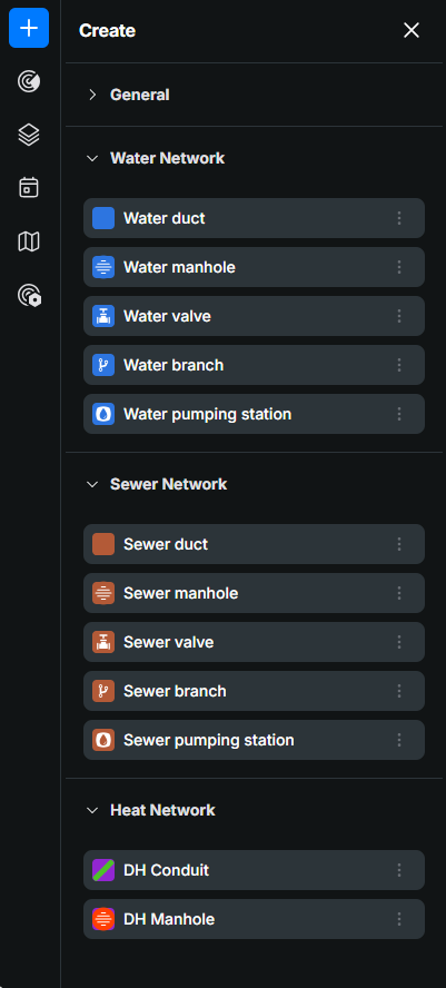
When you click the Create button, Nexus displays a categorized list of object types that can be placed in the network. Each object type represents a specific asset; such as a duct, manhole, valve, branch or pumping station and opens an object pane where its geometry and attribute data can be defined.
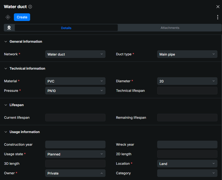
Each object pane also adapts its contents based on the selected object type. For example, Water duct pane provides material and diameter selections and Water manhole
 pane contains lid‑related properties. Each object type mainly displays attributes that are relevant to documenting and managing that particular asset.
Objects are organized by network:
- General
- Water network
- Sewer network
- Heat network (additional)
General structure of the object pane
Every object in KeyAqua Nexus is managed through an object pane that opens when selected from the Createmenu or by selecting an existing object from the map. The object pane allows users to create objects, edit the object’s geometry, update attribute information, and manage related documents.
Although the available fields differ between object types, the structure and functionality of the object pane remain consistent. Each pane contains three tabs:
- Geometry – contains tools for creating and modifying an object’s geometry. The content varies depending on whether the object is a point, line, or polygon, but the workflow is similar for all geometry types.
- Details – contains all attribute information related to the selected object. Fields are grouped into sections that contain information related to the object. Mandatory fields are marked with an asterisk (*).
- Attachments – is used to store external documents related to the object. These may include installation instructions, inspection reports, field photos, permits, or any other supporting files.
Creating a new object
There are several ways you can create new objects in the KeyAqua Nexus system. You can start from scratch or you can use existing objects information as a base for the new object. Always select the correct object from Createmenu. For example, use the Water ductpane to create a new water duct, and the Sewer branch pane to create new sewer branch.
To create a new object in your network, follow these steps:
- Click Create from the KeyAqua Nexus tools.
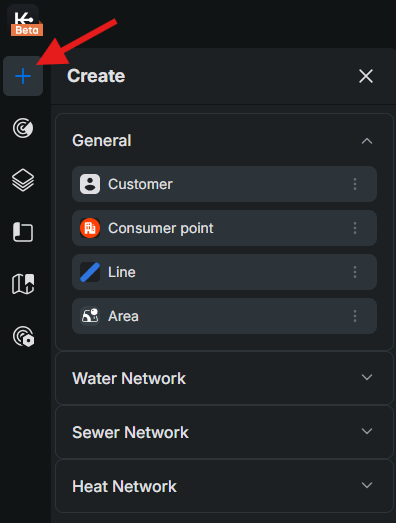
- Choose the correct object pane from one of the four drop-down menus. For example, use the Water ductpane to create a new water duct and use the Sewer branchpane to create a new sewer branch:
- General
- Water network
- Sewer network
- Heat network (additional)
- Specify the location of the object by defining its geometry on the map. Read more: Geometry of a line object and Geometry of a point object.

- By selecting a network object from the drop-down menu, you are also able to edit information of a new network object you are drawing.
- Before clicking Create, you must fill at least all the mandatory fields in the Details (marked with an asterisk (*)) tab:
- Click Create.
Geometry of a line object
- Start defining the geometry of a line object by clicking the required starting point on the map using the left mouse button.
- Continue by digitizing each required point one at a time. Click the left mouse button at each location where the line should change direction or continue.
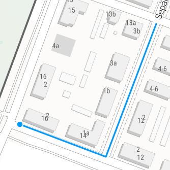
- Finally, end the digitization by clicking the left mouse button twice at point where you want your line object to end.
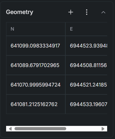
You can also place a line object on the map by entering its coordinates manually. At the top of the menu, you can add a new vertex to the geometry grid by clicking the plus (+) symbol. You can also import or export coordinates to and from the system as needed by clicking More options .
.
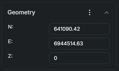
- Enter the longitude coordinate in the N field.
- Enter the latitude coordinate in the E field.
- Enter the height coordinate in the Z field.
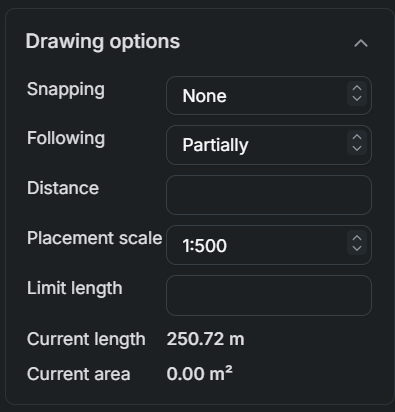
Drawing options of a line object
- From Snapping, you can choose whether the object you create snaps to another object’s point or the nearest point.
- The Following function in the Drawing options allows line objects to follow existing elements, such as ducts. When you select Complete under the Following option, you can point to the starting point of a duct. The line object will then automatically follow the entire path of the duct and continue digitization from its endpoint.
- If you only want the line to follow part of the duct, choose the Partially option. This lets you follow the duct up to a specific point, after which you can continue digitizing freely.
- To draw a line parallel to an object at a defined distance, specify the desired Distance in the drawing settings.
Geometry of a point object
Define the geometry of a point object by clicking the left mouse button at the required location on the map.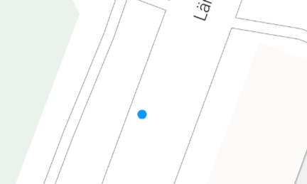
You can also place an object on the map by entering its coordinates manually. You can also import or export coordinates to and from the system as needed by clicking More options.
- Enter the longitude coordinate in the N field.
- Enter the latitude coordinate in the E field.
- Enter the height coordinate in the Z field.
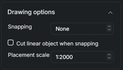
Drawing options of a point object
- From Snapping, you can choose whether the object you create snaps to another object’s point or the nearest point.
- Cut linear object when snapping option allows you to cut a linear object and place.
- From the Placement scale menu, choose the desired scale for object creation. New objects will be sized proportionally according to the selected scale, ensuring they appear correctly in outputs such as printouts—for example, at a 1:2000 scale, individual objects will be clearly visible.