Automated planning refers to the tools available in KeyCom that plan networks automatically. Currently, these tools include Comsof FiberplanIT™ and Setics STTAR.
Automated planning works by exporting the plan and the associated address data from KeyCom to an external system. The transferred data is processed either in the service provider's online service or in a desktop application with the service provider's automated planning extension. The processed results are then brought back to KeyCom for the user to review. The user can then choose to accept the imported files. As a result, various KeyCom network objects (cables, devices and telecom premises) appear on the map.
Setics STTAR (This function is subject to a separate order)
KeyCom's support for Setics STTAR covers exporting the Plan and related objects, exporting the data to the Setics STTAR desktop application, creating the network and importing the final network into the Keycom system using the Spatial upload tool.
tool.
If the Setics STTAR integration is configured in the KeyCom environment, the usage method is the same as the other background data import methods.
- Select Spatial upload

- Select Network as the File type
- Download files
- Select Setics STTAR
Enabling the automated planning
Start automated planning with Setics STARR integration by first creating a new plan for it.
- Open the Plan
 form and create a plan with all the necessary network objects attached to it (Read more in chapter Plans).
 - Open the Setics STARR service form from the Plan
 form toolbar.
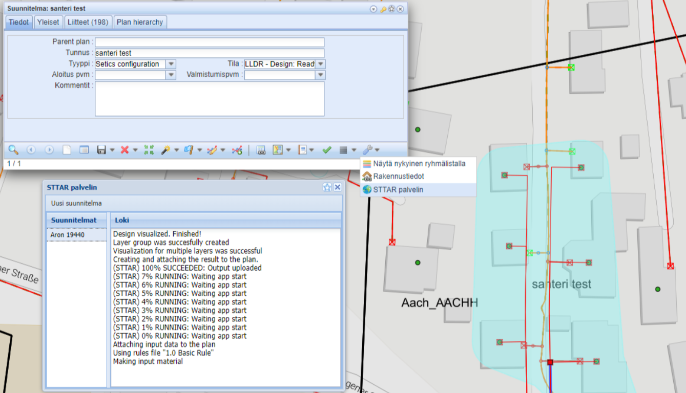
 - Create a new Setics STARR plan within the area of the plan you already created by using the STTAR server form.
Custom preview layer (this function is subjects to a separate order)
Custom Setics STTAR preview layers can be created in KeyCom, which can be defined with text constants in the admin interface.
When creating a new plan, the system creates a completely new layer, which name is defined in the Abbreviation field when creating the text constant (Read more about how to setup Setics STTAR integration and custom preview layers from the KeyCom 3.8.0 setup guide, chapter 21. Automated planning)
Note! The new preview layer is only available for plans created after the feature was enabled.
FiberPlanIT™ by Comsof integration (This function is subject to a separate order)
If the KeyCom system you are using includes the optional FiberPlanIT™ function, you can use it to:
- Export KeyCom network plan data to FiberPlanIT as source information.
- Use the FiberPlanIT software to create an optimised network plan for your area.
- Import the optimised network plan into KeyCom.
- Carry out simple fiber-optic planning using the FiberPlanIT server.
FiberPlanIT is a registered trademark of Comsof N.V. More information on FiberPlanIT is available from your KeyCom retailer, FiberPlanIT user guides, and the following website: http://www.fiberplanit.com.
Exporting a KeyCom network plan to FiberPlanIT
- Open the Plan form in the KeyCom tools, as described in the chapter Plans.
- Create a new network plan or retrieve an existing network plan to the form. When the plan is open on the form, make sure that the area geometry has been created for the plan. If there is no geometry, create it. For more information, please see the chapter Creating a new object.
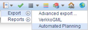
- In the form menu, select Reports > Export > FiberPlanIT (or FiberPlanITServer…). This creates a zip file with the following information:
- The address points within your area (IN_DemandPoints.shp)
- The street center lines crossing your area (IN_StreetCenterLines.shp)
- The existing network pipes crossing your area (IN_ExistingPipes.shp)
- Any exchange telecom premises within your area (IN_CentralOffice.shp)
- The poles within your area (IN_Poles.shp)
Using KeyCom data in FiberPlanIT
- Start Quantum GIS.
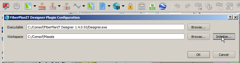
- In the toolbar, click Configure FiberPlanIT Designer
 .
. - Browse and select the installed Designer.exe if necessary.
- Select an empty workspace folder for your network plan.
- Click Initialize.
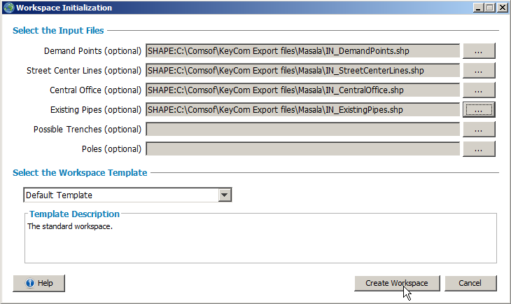
This opens a new browser window. Define the source files as illustrated in the figure. Click Create Workspace.
Import is complete. You can use FiberPlanIT software’s advanced planning automation. When your plan is ready, you can import it back to KeyCom, as described in the chapter Importing a FiberPlanIT network plan to KeyCom.
Importing a FiberPlanIT network plan to KeyCom
Create a zip file of all the files in the output folder of your FiberPlanIT workspace.
- In the toolbar, click Spatial upload
 to manage KeyCom background maps. More information is provided in the chapter Spatial upload.
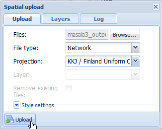
 - Click Browse... on the form. Select the zip file you created as described in the chapter Using KeyCom data in FiberPlanIT.
- Select the coordinate system you used in the FiberPlanIT project. Click Upload
 on the form.
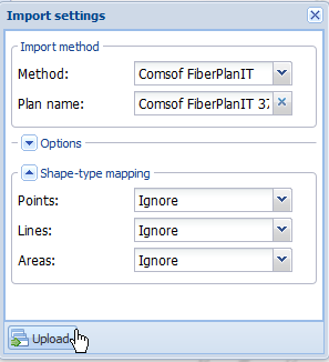
- This opens a new Import settings form. In the Method list, select Comsof FiberPlanIT. You can edit the name of the Plan if you want.
- Click Upload
 on the form to have the import function to create a new network plan with this name.
The file is uploaded in the background without preventing other KeyCom use. It could take dozens of minutes to import a large network plan. When importing is complete, a pop-up window is displayed. Click Yes to zoom the map to the area of the imported plan.
If you want to remove a network plan that was imported from FiberPlanIT to KeyCom, you must first change the plan type to network deconstruction, as described in the chapter Deconstructing a plan. This may be necessary if you want to compare various implementation options in KeyCom. Layer filters are a useful tool when making comparisons. More information on them is provided in the chapter Layer filters.
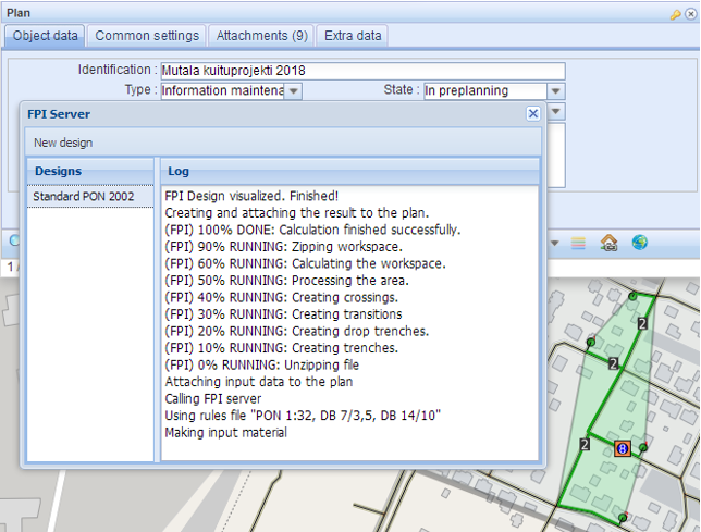
FiberPlanIT server
You can carry out simple fiber-optic planning using the FiberPlanIT server. This server is used through a form that you can open by clicking FiberPlanIT server on the Plan form.
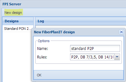
The FiberPlanIT server form lists all fiber-optic planning related to the plan on the left, whereas the event log for active planning is displayed on the right. Start a new plan by clicking the New design button. You can name the planning and define the rule set that is applied. The rule set is for FiberPlanIT, and it includes the applicable parameters. Rule sets can be created and managed through administration.
A valid area licence is a prerequisite for planning. Licences are managed by Comsof. A plan with content that fulfils the requirements described in the chapter Exporting a KeyCom network plan to FiberPlanIT is used as the basis for planning.
The FPI planning is calculated using the applicable rule sets and other default values. A preview of the fiber-optic plan is displayed on the map.
Completed planning can be managed through the context menu for the list on the left:
- You can view or hide the preview layer
- You can delete planning (users can only delete their own plans)
- You can open the bill of materials report that FiberPlanIT calculated for the plan
- You can import a plan as a KeyCom network, as described in the chapter Importing a FiberPlanIT network plan to KeyCom.
You can view the preview layers for all planning under Layers/FiberPlanIT plans in Layers.
Consumers interested in fiber services
On KeyCom's user interface, it is possible to present location information about customers interested in fiber services transmitted from a third-party system. This information can be presented on the map to support planning and guide construction. The REST API interface is used to collect interest information from consumers.
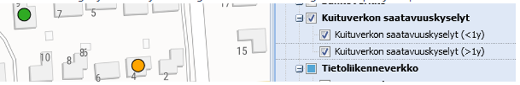
It is possible to implement specific KeyCom fiber network availability layers, which illustrate consumers' interest in fiber services on the KeyCom network map.
In the figure below are fiber network availability queries within less than a year and fiber network availability queries over a period of more than a year are shown on the KeyCom network map in different colors.