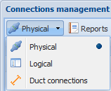
View the physical, logical and duct connections on the Connections management form. You can open this form from the KeyCom and KeyNet toolbars and by clicking Connections management
 on the Splice, Manhole, and Telecom premises forms. You can view the various connections by selecting the required state in the drop-down menu in the top left corner.
Creating connections
You can create a connection by either a) dragging or b) clicking Connect .
.
a) Drag to create a connection:
- Select the object on the list on the left.
- Drag it to the list on the right and position it over the object you want to connect.
b) Click Connect to create a connection:
- Select the object on the list on the left.
- On the list on the right, select the object you want to connect.
- Click Connect.
The program will display a warning if the user is trying to connect objects that have already been connected. You can define additional settings if you create the connections with the Connection options checkbox is selected, or by dragging objects while holding down the SHIFT key. More information on connection options is available in the chapter Options for physical connections.
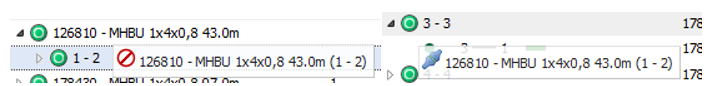
Creating a connection by dragging. On the other list, select the objects you want while holding down the left mouse button. If the dragging function is available, the Connect icon will be displayed. If the symbol
 is displayed next to the icon, the connection will not be made. Drag the icon to the other list while holding down the left mouse button, and then release it.
Disconnecting connections
You can disconnect connections either individually or by selecting at the higher list level all connections related to the selection (such as all the connections of a device).
- Select from which or what is disconnected.
- Click Disconnect
 .
.
Or
- In the context menu, select Disconnect
 .
. - You will be asked to confirm the disconnection. You can either accept or reject the disconnection.
Note! The software will notify you if the thread or thread connection has been reserved for a circuit. The form that is opened prompts you to choose which connections to disconnect. Confirm the disconnection or click Cancel.
Picking objects to the connections management form
- Click Pick from map
 .
. - Define the map area that you want to use for picking objects.
- On the selection list for the object, select the required object. If there is only one object in the defined area, it is automatically picked to the Connections management form.
Synchronize
Use synchronization if you want to illustrate the connections between the objects. Select a device a cable on the list and click Synchronize or click the object with the right mouse button and select Synchronize. When an object has been synchronized, the object connected to it is highlighted on the list.
Refresh
Use the Refresh tool to refresh the connection tree content to match the changes you made on the Telecom premises, Device, and Connections management forms.
Managing physical connections
The button for managing physical connections is available under the KeyCom menu and on the Telecom premises, Manhole, and Splice forms. Click it to open the Connections management form. The general functions for connections management are introduced in the chapter Connections management.
The two lists on the form include the devices and cables. The information content of the lists is similar, but the list views may be different. The related tools Disconnect and Synchronize
 are applied to the object selected in the list above them. Connect
 requires information on two objects in order to create a connection.

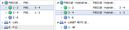
Each cable or device ID is preceded by a symbol that indicates whether it is a cable (a round symbol) or a device (an angular symbol). Objects in copper or electrical networks are marked in green colour, while blue colour is used for fiber-optic networks. Hybrid networks are marked with both colours. Click the arrow in front of the symbol to view the devices and threads connected to the object in question. You can hide the objects by clicking the same arrow. The Connected to column displays the ID of the device or cable to which the device or cable in question is connected.
Click a cable or device using the right mouse button to open a menu that includes the form functions and enables highlighting or locating the listed cables and devices.
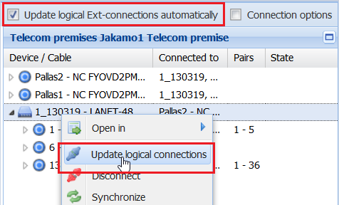
Update logical connections automatically
When physical connections are created with the Update logical Ext-connections automatically option enabled, the program will also update the logical connections that are not reserved for circuits and the attenuations based on cable connections. This function is used to automate the Update logical connections function, which is available when right-clicking a device.
Note! The functionality does not extend to cable connections that are not connected to devices (for example, splices).
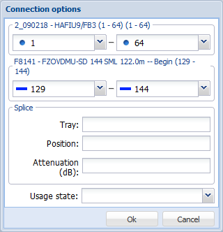
Physical connection options
You can open the Update connections form if you create the connections while the Connection options checkbox is selected (in the top-right corner of the form), or by dragging while holding down the SHIFT key. On the form, you can define the connections of the various threads in a cable bundle and you can enter additional information on the connections in the following fields: Tray, Position, and Attenuation (attenuation in a fiber-optic cable). In addition, in the Usage state drop-down menu, you can define the usage state of the connection.
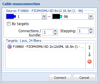
Physical mass connection
Select multiple items to carry out a cable mass connection:
- In the Connections management window, select the Connections options checkbox.
- Select the source cable on the list on the left.
- Select the cables you want to connect on the list on the right.
- Click Connect.
- In the Cable mass connection form, define the settings for a mass connection.
- Click Connect.
Context menu functions for devices
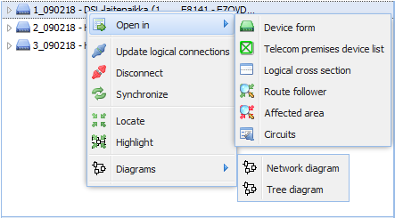
You can find the following functions in the context menu that you can open when clicking a device with the right mouse button:
- Open in Device form: Opens the Device
 form. More information on devices is provided in the chapter Devices.
 - Telecom premises device list: Opens the Telecom premises form and displays the Devices tab. More information is provided in the chapter Devices.
- Logical cross section: Opens the device on the Logical cross section report of the telecom premises and selects the correct device from the list. See the chapter Cross-section.
- Route follower: Opens the Route follower form that has been set up for route following. See the chapter Route follower.
- Affected area: Opens a Route follower form pre-completed with the selected device’s connectors and cables connected to the connectors. The route follower highlights the connection routes that are connected to the selected device either directly or over logical cross-connections.
- Circuits: Opens all circuits related to the device’s connectors.
- Update logical connections: Creates or updates the logical connections for the device selected based on the physical cable connections.
- Disconnect: Disconnects all the connections of the device.
- Locate: Locates the device on the map based on the telecom premises.
- Highlight: Highlights the telecom premises of the device on the map.
- Diagrams: Creates a network diagram or a tree diagram. More information is available in the chapter Diagrams.
Context menu functions for connection bundles

You can find the following functions in the context menu that you can open when clicking a connection bundle with the right mouse button:
- Edit: Opens Update connections form where you can edit the splice tray, position, attenuation (dB) and usage state.
- Open in – Route follower: Opens the Route follower form that has been set up to find routes based on the bundle range. See the chapter Route follower.
- Open in – Circuits: Displays all circuits of a connection bundle.
- Disconnect: Disconnects a connection.
- Synchronize: Synchronizes one of the lists to display the other end of the connection.
- Locate: Locates an object on the map.
- Highlight: Highlights an object on the map.
- Diagrams: Creates a network diagram or a tree diagram. More information is available in the chapter Diagrams.
Context menu functions for a fiber-optic cable/pair/connector

You can find the following functions in the context menu that you can open when clicking a fiber-optic cable/pair/connector with the right mouse button:
- Open in – Route follower: Opens the Route follower form that has been set up for route following using the selected fiber-optic cable/pair/connector. See the chapter Route follower.
- Open in – Circuits: Displays the circuits related to the thread or connector.
- Disconnect: Disconnects the connection for the selected pair, fiber-optic cable or connector.
- Synchronize: Synchronizes one of the lists to display the other end of the connection.
- Locate: Locates an object on the map.
- Highlight: Highlights an object on the map.
- Diagrams: Creates a network diagram or a tree diagram. More information is available in the chapter Diagrams.
Context menu for a cable
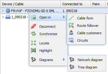
You can find the following functions in the context menu that you can open when clicking a cable with the right mouse button:
- Open in – Cable form: Opens the Cable form.
- Open in – Route follower: Opens the Route follower form that has been set up for route following based on a cable. See the chapter Route follower.
- Open in – Cable customers: Opens the Cable customers form on which you can view the customer information for the fibers of the cable/pairs.
- Open in – Circuits: Displays all circuits related to a cable’s threads.
- Disconnect: Disconnects all connections for the cable in question.
- Synchronize: Synchronizes one of the lists to display the other end of the connection.
- Locate: Locates the cable on the map.
- Highlight: Highlights the cable on the map.
- Diagram: Creates a network diagram or a tree diagram. More information is available in the chapter Diagrams.
Thread connections report
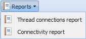
On the Connections management form, in the state Physical, click Reports , and select Thread connections report (* MERGEFORMAT ). The report is created in Excel format, and it includes tabs on which the connections are presented with and without connectors. If you are using a fiber-optic cable for which colour coding has been defined in the database, this colour coding is also visible in the report.
Duct connections management
Use the Duct connections function to connect ducts to other ducts or sub-ducts in a manhole. This is often required when there is a branch in a duct line or the duct profile changes. You can manage duct cross-connections on the Connections management form with the Duct connections
 function.
- Open Connections management.
- In the menu for the form, select Duct connections
 .
. - The basic functions of this form are explained in the chapter Connections management.
- Below the conduit/duct list, there is a cross-section of the selected conduit, in which the selected duct is highlighted.
