The form for managing district heating conduits is opened with the District heating conduit  button.
The Conduit form
The District heating conduit form can be used to retrieve or update information about conduits and add new ones. When creating a new conduit, you must first fill out at least the required property information on the form. Required fields are marked with an asterisk (*) on the form. The Shell structure option is shown in a graphical format on the form. The value generated in the Heat loss field is based on the shell structure and the size of the duct.
You can add information such as accuracy of location on the Common tab, while the Extra data tab can host free-form text.

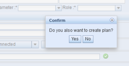
The system allows creating a new plan automatically when creating a new conduit. A buffer area of the plan is created around the conduit and is linked to that conduit. After saving or creating a geometry for the conduit the pop-up window will appear where you can decide whether to create the plan or not.
The new plan will copy Identification, Network Type, Type, Usage state and Install year from the District heating  form. If you decide to split the conduit, the plan will be then linked to both new conduits.
NOTE! This function does not apply when updating an existing conduit!
Selecting outlet and inlet ducts
Outlet and inlet ducts must also be selected for the conduit before the conduit is placed anywhere. To do this, select Material, Diameter, and Role information from the drop-down menus. You can also search existing conduits by first choosing the options form the drop-down menus and then clicking Search  button from the toolbar. The role refers to either an output, input, or protective duct. To store the selected data in the database, click the Add duct
  button. You can also select the data with the Duct defaults
  button, which will show the data of the default ducts on the form and save it in the database.
To change duct data, first select the data of the desired duct by left-clicking it and then select the desired data in the drop-down menu. Click the Update duct  button to save the data in the database. To completely remove a duct from the database, select its data and then click the Delete duct
  button.

Digitizing conduits
When creating a new conduit, it is possible to snap to manholes, i.e., connect the conduit to them.
After filling in the required data, click Create new  to create an object on the map. The Drawing options window appears. To automatically place the conduit start and end at the same location as existing objects, use the Snapping function in the Drawing options window. To do this, hold down the Shift key on the keyboard when clicking the left mouse button on the manhole. If snapping was successful, the bottom bar will read: Snapping completed. If the bottom bar reads: Snapping failed, it is not possible to snap to the object in question. When the Snapping function is active, the mouse pointer is shown as a light-blue circle.

You can also use the Following function in the Drawing options window to follow existing objects either partially or fully. Finally, end the conduit digitization by first clicking the left mouse button at the end point of the duct and then the right mouse button. If the end of the conduit is also placed in the same position as an existing manhole, hold down the Shift key, click the left mouse button, and then click the right button. The conduit’s location and property values are saved in the database.
Connecting a conduit
A conduit’s connections to manholes are displayed at the bottom of the form. A conduit can be connected to a manhole at both ends or only at one end. If the conduit is connected, the menu text shows the manhole and possibly its ID, otherwise the mode is Not connected. You can access the connections in the drop-down menus. Click Disconnect to disconnect a connection. When this has been successfully carried out, you can see the following text at the bottom of the form: Conduit successfully disconnected. Select Modify to open the form for the manhole in question. You can then view its information or locate it on the map.

To connect a conduit, click the Select node option and then select the manhole to be connected on the map. If the selection is made from the first drop-down menu, the program automatically assigns the beginning of the conduit as the default object of the connection.

Correspondingly, if the selection is made from the second drop-down menu, the program automatically assigns the end of the conduit as the object of the connection. Confirm your selection by pointing at a location using the left mouse button or select another manhole. The selection can also be made by cropping the area with the left mouse button. Regardless of the method of selection, the Object selection window appears after selecting. Click a manhole with the left mouse button to select the manhole on the map. This makes it easier to select the correct manhole. Create a connection by clicking the node with the right mouse button and then select Connect to conduit. If the connection succeeds, the following text will be displayed on the form: Conduit connected successfully, and the details of the manhole appear in the Connections menu.
Splitting conduits
It is possible to split a conduit by using the Split function on the Modify menu. When you click the Disconnect button, a dialog opens where you select the node you want to add to the split.

When the desired node is selected, the program asks you to indicate the conduit’s split point. Splitting is done by taking the mouse pointer to the desired position on the conduit and then clicking with the left mouse button to accept the split. The program then performs the split and adds the previously configured node to the split point. The split conduit is automatically connected to the node, so it is not necessary to do the connection separately.