Exporting to Finnish VerkkoGML
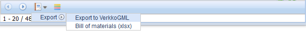
Finnish VerkkoGML models the network objects’ location and primary features. This data model is used for transferring network information between various systems. The data model has been described as a UML diagram and XML schemas. The schemas comply with the ISO 19136 GML standard. Data classification is based on the classification of municipal location information and is compatible with the Finnish KuntaGML data model. You can export objects listed using the Info tool to a VerkkoGML file. To do this, click Export and then select the Export to VerkkoGML function. If your browser suggests saving the file, do this to minimise any problems.
You can also export to VerkkoGML objects included in a plan you selected on the Plan form.
The VerkkoGML function is also available on all object forms (cable, conduit, splice, pole, manhole, telecom premises) and on the circuit form. This function creates a VerkkoGML file of the
Exporting objects to external file formats
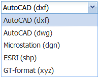
You can export KeyCom objects to AutoCAD (dwg, dxf), ESRI (shp), Microstation (dgn), and GT (xyz) formats. You can also export area objects and the area borders of plans to these formats.
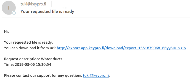
Use either the Info form or the object forms to export network and annotation data to one of the formats listed above. The link for downloading is sent to the user’s email address.
- In the drop-down menu for Export
 , select Export – Advanced export... to export the objects to another file format.
 - On the Export settings form that appears, select the export Format.
- Enter a Description for the export and select the required coordinate system (Projection) for the file that is created.
- Use the Crop to border option to select whether to crop objects along the borders of area objects.
- Select whether annotations are exported.
Note! Email addresses are defined/linked to user IDs through the admin user interface. If the intention is that a user does not have rights to use this function, the email address field must be left empty.
Admin users can edit the email address to which the link for downloading data is sent.
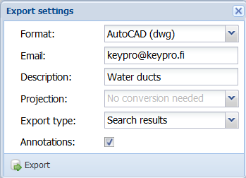
- Click Export to accept the data export
 . The system displays a notification that your request is being processed.
In the picture below, request is pending.
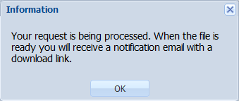
When the file has been processed, the system will email the user a link for downloading the file.
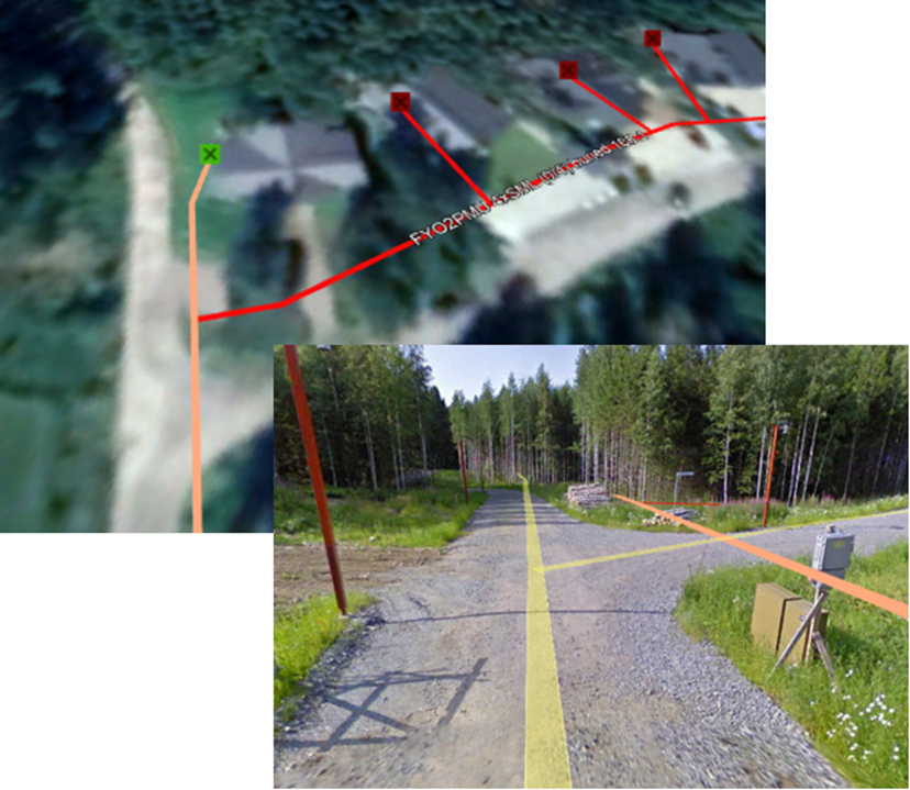
Keyhole Markup Language (KML) is an XML-based mark-up language. KMZ is a compressed KML file, or a set of files. Google Earth and Google Maps support KML and KMZ files, enabling the use of the file content, for example, when checking the location of cables. Exports to these file formats can also be viewed, for example, in QGIS, which displays the basic information on the object properties.
KML exports are enabled for the following network objects: cables, ducts, telecom premises, splices, manholes, poles, and point objects. Various symbols are used for displaying point objects, with different colours used for line objects.
TIP: If you want to view the exported material in Google’s map applications, we recommend that you select WGS84 as the coordinate system. In addition, please note the service terms applicable to material loaded to Google.
Importing by using the Spatial upload tool (This function is subject to a separate order.)
Add background maps using the Spatial upload tool. Organize and add new background maps to the background layer levels and specify the symbology* for imported files (*Esri™ SHP only). Background maps imported into the system are shared or available for a specific group or user. First, in the main toolbar, click Spatial upload
 .
.
The Spatial upload tool supports the following file formats for creating background maps:
- Esri™ SHP
- Bentley MicroStation™ DGN (V8)
- Autodesk AutoCAD™ DWG
- CSV files (X;Y; name; color; size), see the chapter CSV file format.
In addition, you can create network objects directly from files in the Esri™ SHP format (network). More information on this is provided in the Uploading network objects chapter (Settings must be configured through the admin user interface.).
Managing layers
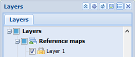
To upload background maps, select an existing layer or create a new background layer on the Layers tab. To create a background map layer, enter its name in the Layer name field and click Add layer . The layer appears in the Reference maps section on the Layers form. You can organize the background map layers and their hierarchy.

The user-created layer is now visible under the Reference maps layer.
You can create user-specific or group-specific background maps. Any layers you create will be shared by default and will be marked with the unlocked lock icon . You can define a layer as private by selecting the checkbox. The icon will be replaced with a locked lock
 and the layer you created will not be visible to others. When you have defined the level you created as private, the Groups checkbox will be activated. If you want a specific group to see the background map you created, select the name of the group in the drop-down menu for Group. Admin users can create groups and add users to the groups.
Spatial upload
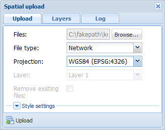
- Select the Upload tab.
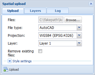
- Click Browse and select the file you want to upload.
- If you are uploading an ESRI shp file, also select the dbf file.
- Check the file type before uploading. This field is usually filled in automatically so that it matches the file you selected.
- Select the projection applicable to the file that is uploaded.
- Select the background map layer to which your file is added.
- Select Remove existing files if you want the layer to include only the data included in the files you are uploading (as if you would first delete all files from the layer in question, see the chapter Deleting reference maps).
- Define the style settings applicable to the object types (Esri™ SHP only).
- Click Upload
 . The progress bar indicates the status of the file upload. Note that it could take several minutes to upload a large file. TIP: If your file includes objects with various style settings, you might have to separate them into different files based on their symbology.
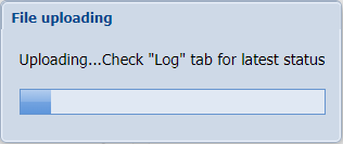
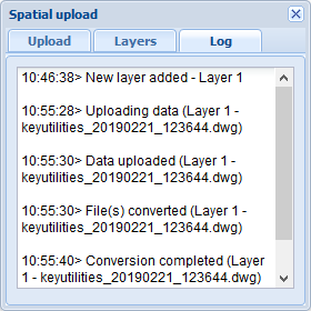
- Browse the the Log tab for a file upload.
- When the file upload is complete, the following notification is displayed: Data is ready, zoom to extent? Click Zoom and check the result on the map.
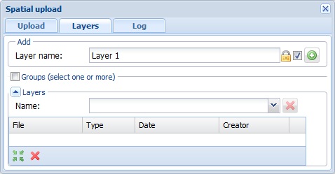
When the file has been uploaded, it appears in the Layers section on the Layers tab of the Spatial upload form: 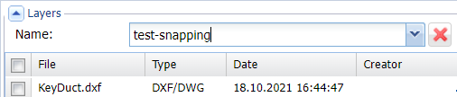
Note! When you create new network objects, you can use the snapping function on the background map.
Deleting background maps
- Select the Layers tab.
- Expand the Layers section if it is hidden.
- In the drop-down menu for Name, select the layer where the background map you want to delete is located.
- Select the file you want to delete and click Delete selected files
 .
.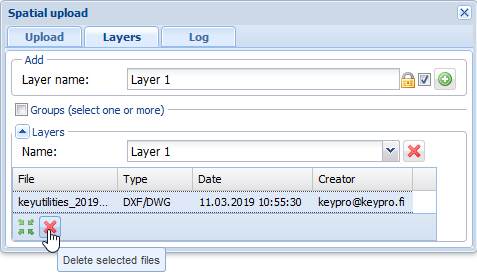
- Confirm and check the result on the map.
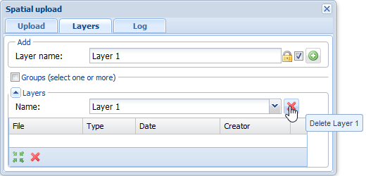
Deleting a background map layer
- Select the Layers tab.
- In the drop-down menu for Name, select the layer you want to delete.
- Click Delete
- If there are files attached to the level, the following notification will be displayed: Layer If you are sure that you know what you are doing and you still want to delete the layer, click Delete to confirm the action.
Material in CSV format
Rules for importing CSV files:
- Fields are separated by semicolons (*;*).
- No column headers are used.
- Rows are in the following format: X;Y;[TEXT];[COLOUR];[SIZE]
- The TEXT, COLOUR, AND SIZE columns can be empty.
- If TEXT is empty, a point object is created. Otherwise, free text is created.
- If COLOUR or SIZE is empty, default values are applied.
- COLOUR is an RGB value, such as “255 255 0”.
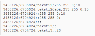
TIP: If you want to create both point objects and free text, create two versions of the file – one containing the texts and another where text boxes are empty – and upload both files to the same layer.
Uploading network objects (Settings must be configured through the admin user interface)
- Select shp and dbf files, or a zip file containing such files, as the files.
- Select Network as the file type.
- Click Upload
 .
. - On the Import settings form, select Method.
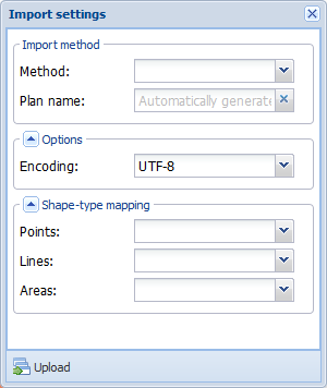
- Check that the mappings are correct.
- Click Upload
 . The progress bar indicates the status of the file upload. Note that it could take several minutes to upload a large file.
 - When the file upload is complete, the following notification is displayed: Data is ready, zoom to extent? Click Zoom and check the result.