You can use the Plan field of an object form to attach the object to a Plan  . If a plan does not yet exist, you can create one on the Plan
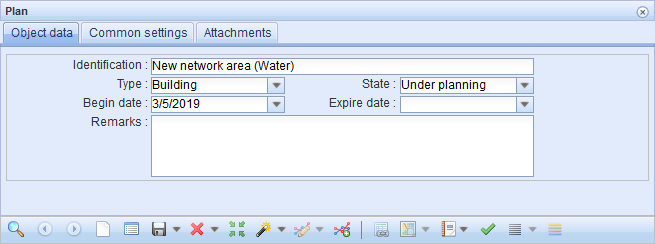
 form. The mandatory fields for a new plan are type, state, and identification. Give an identifiable name for you plans, because plans are selected to other forms based on their identification. It is important to save an area for a plan. Saving an area is a prerequisite for using a plan as input for automatic fiber-optic planning. For more information, see the chapter Integration with FiberPlanIT™ by Comsof (This function is subject to a separate order).
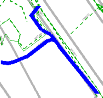
Click Create  and digitize the border of the area. Instructions on this are available in the chapter Modifying the geometry of an area. Stop digitizing and save by clicking the right mouse button. After you have created the plan and saved it in the system by clicking Save form
  , it is available for selection in the Plan field of object forms.
Set as the default plan
Click Set as default Plan  to set a plan retrieved to a form as the default plan. When you click Defaults on object forms, the default plan is automatically added to the form. You can cancel the Default plan setting in the Defaults
  menu. See the chapter Managing settings defined by a user.
Locating a plan
Click Locate  to locate a plan and the related objects.
TIP: Define the location of the plan so that you position the plan on the map already before adding any objects to it.
Highlighting objects
Objects that are part of a plan can be highlighted on the map by clicking Highlight . This centers the map on the objects included in the plan and highlights the objects on the map.
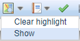
To view a plan’s objects on the map, select Show in the drop-down menu for Highlight  to activate the Plan filter in the Layers (Filters) selection and to display only the objects of this plan on the map. More information on filters is available in the chapter Layer configurations.
You can save a Layer configuration, that is the selected background map and the active layers, by clicking Save  in the top-right corner of the Layers tool. Layer configurations are saved in the browser cache of the browser that was used, and they are, therefore, not available on other computers.
Layer configurations can also be saved in a database with a user name, in which case the layer configuration is user-specific instead of browser-specific. Save a layer configuration in a database by clicking Configure and wait for the background colour to change to orange. Click Save
  to save the layer configuration in a database.
Upload the saved layer configuration in the Layers form by clicking Reload . You can restore the original layer configuration settings by clicking Reset to defaults
 . The program displays the following notification: User preferences will be deleted and default configuration will be loaded.
TIP: You can view all objects by removing the Plan filter on the Filters tab of the Layers form.
Adding an object to a plan
Use the objects’ own forms to add objects to plans.
- Open an object form.
- Retrieve the object you want to add to the form (Retrieving information to a form, orPicking objects from the map), or fill in the information on the new object.
- Select the required plan from the drop-down menu in the Plan field OR:
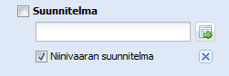
Retrieve the appropriate plan to the Plan field (Using the predictive search field).

- Click Save
 .
.
TIP: Plans that are marked to be ready are displayed as search results for the predictive search field if you select the All checkbox.
Maintenance state of plan objects (this function is subject to a separate order)
The usage state of objects that belong to a plan can be locked if the related function has been enabled on the basis of a separate order. If a plan is in the maintenance state, users cannot update the network object included in the plan, and they cannot delete the plan. Network objects that can be locked include cables, conduits, ducts, telecom premises, devices, splices, manholes, poles, and other point objects and connections at the cable and device levels.
The admin site is used to specify the user group with the right to set plans to the maintenance state. However, all users can modify the property attributes and location information of plans in the maintenance state, excluding the usage state of the plans.
List the objects of the plan
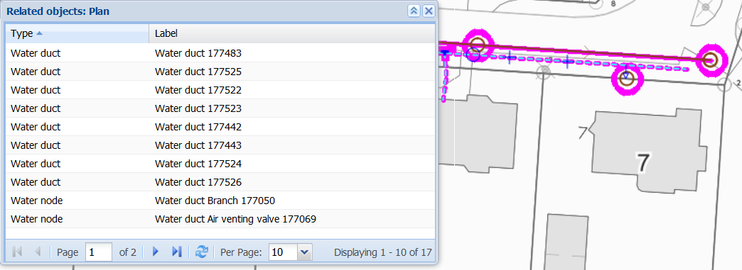
Click List objects of the plan  to view information on a plan’s objects. Clicking this button opens a list of the objects related to the plan, including the type, identification and description of the objects. Click the right mouse button over the target row to click Show on the form. This takes you to the object form. You can view or edit an object’s information on the object form.
Completing plans
When you edit the State of a plan, you can update the objects related to the plan.
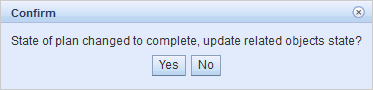
Use this function when a network with objects in the Planned state has been planned on the map. When the plan is implemented and completed, the usage state of its objects should be updated to In use. Open the appropriate plan on its form and change the usage state to Ready. Then click Save form. The program will then ask: State of plan changed to complete, update related objects state? Click Yes to update the state of the related objects to In use.
Deconstructing a plan
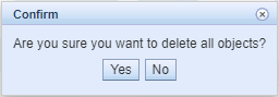
You can also use the Plan tool for planning the deconstruction of a plan. In deconstruction plans, set Deconstruction as the Type of the plan. Deconstruction plans function in the same way as normal plans, in addition to which any objects linked to the plan when it was completed can automatically be removed from the map (deconstructed), or their usage state can be set to scrap. Note that you must mark the State of the plan as Ready.
List the apartments and addresses in the plan
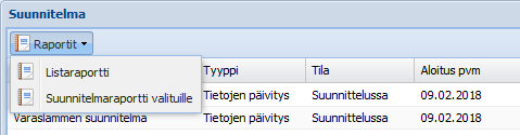
In the drop-down menu for List  , select Plan apartments to view a list of the plan’s addresses and apartments. This list displays the number of apartments and all the basic information on the Address and Apartment forms can be selected for a column view. In the menu for the Reports button, click List report
  to create a list report.
In addition, you can list the addresses related to the plan (Plan addresses), the properties related to the plan (Intersected properties), or the properties related to all plans retrieved to the form (Intersected properties for all).
Further information on the list view is provided in the List chapter.
Plan report
The plan report (an Excel document) includes all the objects related to the plan. Furthermore, the plan report includes the role of the cable and the number of connected threads, as well as the conduits’ and ducts’ distances eligible for subsidy (if the feature Distance eligible for subsidy has been ordered).
You can create a plan report for more than one plan. On the Plan form, select List . On the displayed form, select the required plans by clicking the rows with the left mouse button while holding down the Control/Shift key. Open the Reports
 drop-down menu and select Plan report for selected. The header field of the Excel report includes the names of the selected plans.
Tukikelvottomien sijaintien vienti (Erikseen tilattava toiminto)
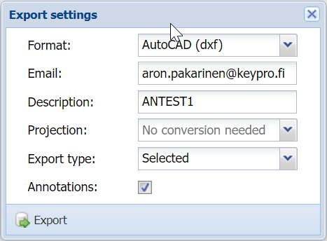
Voit viedä kaapelien ja kanavien tukikelvottomat sijainnit ulkoisiin tiedostomuotoihin valitsemalla Raportit  -alasvetovalikosta Vie-toiminto. Vientiasetuksissa määrittele Vientityyppi-valikkoon Tukikelvottomat sijainnit. Kaapelin ja kanavan tukikelvoton sijainti muodostuu niistä osista, jotka kulkevat tukikelvottomien alueiden läpi.
Show in group display
Click Show current in group display to open the plan’s objects in a group display. More information on the group display is available in the chapter Group display.